(C) 2024, G. Forrest Cook
100:1 High Voltage Probe Assembly

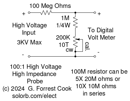
100:1 High Voltage Probe Schematic
This project involves the construction of a calibrated 100:1 ratio high voltage probe that can be used to extend the range of a digital volt meter from a maximum of 1KV to several KV. It has an impedance of over 100 Meg ohms, making it suitable for measuring high impedance, high voltage sources.
The probe circuit was built for testing the 900V power supply in Geiger counters, these supplies have a very high impedance. A standard digital volt meter has a much lower input impedance and will load the power supply down, giving very inaccurate results. The probe can also be used for measuring other high voltage supplies such as those that might be found in high-powered radio transmitters.
This probe is intended to be connected to high voltage sources in excess of 1000V. Extreme caution should be observed when working with these voltages, especially if the voltage source can produce lethal high currents. The high voltage side of the probe should only be connected to the high voltage source when the source is powered off and shorted to ground. All of the external probe wiring should use wire that has insulation that is rated above the voltage to be measured. This probe should only be used by someone who is familiar with working with high voltages, proceed carefully and at your own risk.
The probe uses a very basic voltage divider circuit with a ratio of 100:1. The voltage to be measured enters the divider through a 100M ohm high voltage resistor that is in series with around 1.1M ohms of resistance to ground. The digital volt meter is connected across the 1.1M ohm resistance where is sees the input voltage divided by a factor of 100.
The 1.1M ohm resistance consists of a 1M resistor in series with a 200K or 250K trimmer resistor. The trimmer resistor allows the probe to be calibrated to a known voltage source. Note that the calibration will likely change with different meters since their input impedance may vary.
The probe should be built into an insulated plastic box, do not build this in a metal box or arcing is likely to occur. The positive high voltage input comes into the box through a banana jack (red in the photo) and connects to the 100M ohm resistor. The negative high voltage input comes into another banana jack and connects to the negative meter pin jack. Be sure to give the maximum possible spacing between the two input jacks.
The other end of the 100M ohm resistor connects to the meter + pin jack (yellow in the photo). The 1M ohm resistor and 250K calibration trimmer are soldered in series and connect across the meter + pin jack and meter - pin jack.
The 100M ohm resistor used in this project was a glass-encased Victoreen 1% tolerance part that your author had in his parts collection. These are rare and expensive parts, they can probably be found on eBay. Suitable substitutes would be a string of five 20M ohm 1/4W 5% resistors or ten 10M ohm 1/4W 5% resistors. 10M ohm resistors are more common and less expensive than 20M parts. The resistor string should be soldered together and inserted in a piece of insulated plastic tubing.
Single resistors have a maximum voltage rating before the parts flash-over, be sure not to exceed this voltage on any individual part. The maximum string voltage is the rated resistor voltage multiplied by the number of resistors in the string. Be sure to avoid sharp points on all solder joints, those can cause arcing.
Calibration of the probe requires a high voltage supply that produces between several hundred and one thousand volts. A vacuum tube radio or guitar amp can be used to produce the calibration voltage. The digital volt meter should be rated to measure this voltage directly. A Fluke 77 DVM was used for calibrating this probe. The Fluke meter has an imput impedance of around 10M ohms, this becomes part of the resistance on the lower half of the voltage divider.
Measure your calibration supply and record the value. For this example, say that the supply reads 350V on your DVM. Plug the DVM into the probe output and connect the probe input to the (turned off) calibration supply. Turn on the calibration supply and observe the DVM reading, it should be somewhere around 3.5V. Adjust the calibration trimmer until the DVM reads 3.50V, or whatever the actual measured voltage is divided by 100. Double-check the readings with and without the probe to make sure they agree.
As an extra check on the calibration, you may want to directly measure the calibration voltage with and without the 100M ohm probe input connected. If the voltage changes, use the voltage with the 100M ohm probe connected as the reference value. Most high voltage supplies will not change much with a 100M ohm load.
Plug your DVM into the probe's output jacks and set it to read DC volts. Connect the high voltage leads to the high voltage source wiring with the power turned off. Be sure to momentarily short the high voltage source to ground to discharge any capacitors. Remove the short and turn the high voltage source on, observe the voltage on the DVM. Multiply this reading by 1000 to get the actual voltage.
This probe can be used to measure AC volts, however it will need to be re-calibrated to compensate for differences in the DVM's AC and DC impedances. A switch could be added to select differt calibration trimmers for AC and DC readings.
Back to FC's Test Equipment Circuits page.