(C) 2026, G. Forrest Cook
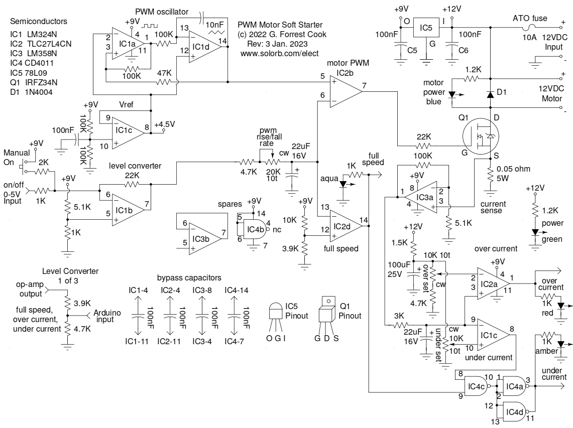
This circuit controlls a DC motor with both manual and automatic switching. It is typically used for controlling a DC water pump. The circuit features pulse width modulation (PWM) starting and stopping of the motor for gradually speeding up and and slowing down the motor. This can help to prolong the life of the motor and reduce stress on the mechanical components.
The circuit features a TTL-level digital input and TTL-level outputs which can be connected to a microcontroller such as an Arduino or Raspberry Pi for automated operation. There are three motor status indicators with associated digital outputs for indicating full-speed, over-current (pump blocked) and under-current (pump dry).
The circuit has been used for controlling a 12 Volt marine bilge pump which is used for transferring water through a solar water panel and a radiator. It can also be used for a variety of other applications that require gradual starting and stopping of a motor.
Power for the circuit is supplied by an external 12VDC supply such as an AC operated supply or a solar-charged 12V battery, the supply should have a current rating that is sufficient to run the motor under fully loaded conditions.
The pump motor connects to the circuit using a pull-down MOSFET transistor, the motor leads should be floating (non-grounded).
A TTL-level (0-5VDC) signal is used for turning the pump motor on and off, this can come from a microcontroller or a circuit such as a Differential Temperature Controller using a resistive divider logic level converter.
Three TTL-level motor status signals are produced by this circuit: full-speed, over-current and under-current. These signals are fed back to an associated microcontroller and can be used by the software for displaying the motor status and automatically shutting down the motor when a fault condition arises.
There is a manual push-button that can be used to turn the pump motor on, this can be useful for initially circulating water through the system and calibrating the over and under current indicators.
There are five status LEDs in the circuit:
12VDC power is provided to the circuit through a 10 amp safety fuse. A 78L09 regulator IC produces 9VDC regulated power for running the analog and digital circuitry.
A free-running square/triangle wave oscillator using IC1a, IC1c and IC1d is used for generating the pulse-width modulation signal. IC2b is wired as a voltage comparator and produces a pulse-width modulated square wave on its output.
The pulse width from IC2b is controlled by the on/off signal entering IC1b. When the input to IC1b is pulled high, the output of IC1b drops and the R-C network consisting of a 4.7K resistor and 20K pwm rise/fall trimmer and a 22uF capacitor produces a slowly dropping voltage. This causes the output of IC2b to produce a gradually increasing pulse width, ending with the output fully on. When the input to IC1b is pulled low, the pulse width gradually decreases until the output of IC2b turns fully off.
The IC2b pulse-width signal is used to drive the power MOSFET transistor Q1. The 22K resistor on the gate of Q2 in conjuntion with the Q2 gate capacitance lowers the pwm rise/fall times to reduce the generation of radio frequency interference from the motor circuitry.
The 0.05 ohm resistor on the source pin of Q1 produces a voltage that is proportional to the motor current. This signal is amplified by IC3a and is fed to comparators IC2a and IC1c, which sense when the current is above or below the normal operating levels. The 3K/22uF RC network between the output of IC3a and the inputs of IC2a and IC1c act as a low-pass filter for de-sensitizing the two comparators, preventing them from reacting to brief changes in the motor current. The two comparators drive the associated status LEDs and their 0-9VDC outputs are sent through two resistive dividers to produce TTL-level signals for the microcontroller.
IC4a, IC4c and IC4d are wired to produce an AND gate function which assures that the under-current signal only passes through when the motor is up to speed. This prevents a false indication when the motor is ramping up to speed.
IC2d is wired as a fixed voltage comparator that turns on when the PWM control input reaches the fully on condition. The output of IC2d drives a status LED and goes through a resistive divider to produce a TTL-level signal for the microprocessor.
The circuit was built on a perforated board using sockets for the three ICs. Wiring was done using 28 gauge solid insulated wire to make the various point-to-point connections. The high current wiring between the power supply input, the motor output and the switching MOSFET was done using 16 gauge wiring.
Calibration of the circuit should be done when the circuit is first built and also when a new pump is installed. The various calibration steps should all be done using the manual-on pushbutton.
In the typical water pumping application, the pump should be filled with water. A bilge pump can be temprarily run inside of a bucket that is partially filled with water, avoid getting the motor internals and wiring wet.
The pwm rise/fall trimmer should be set for the desired motor ramp up and ramp down charachteristics. A typical motor start/stop rate will be somewhere around a tenth to one half of a second.
To adjust the over-current indicator, press the manual on pushbutton and adjust the over-set trimmer so that the associated LED comes on when the motor is running and the output of the pump is blocked. Blocking the pump can be done with your thumb, or with a shutoff valve if you have one in your system.
To adjust the under-current indicator, press the manual on pushbutton and adjust the under-set trimmer so that the associated LED comes on when the motor is removed from the bucket and allowed to run dry.
As shown, this circuit is normally used in conjunction with an external microcontroller which handles the logic of turning the motor off if over current and under current errors are detected. If it is desirable to add these features to a stand-alone version of the circuit, it can be easily accomplished with the addition of a few parts.
Two 2N3904 transistors can be wired as pull-down inverters. The two emitters should be connected to ground. The two bases can be connected to the 9V over current and under current signals through 10K resistors. The two collectors can be tied together and attached to IC1b pin 6. This will cause either error condition to automatically shut the motor off. The connection between the two collectors and IC1b pin 6 should be switched on and off with a jumper, the jumper should be removed during calibration of the over and under current level trimmers.
Back to FC's PWM Circuits page.