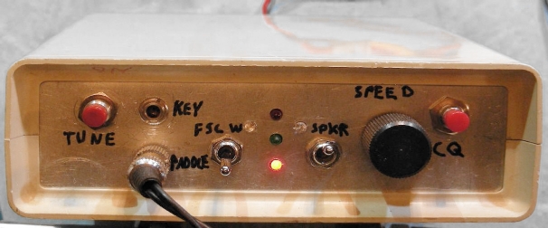
The SibKeyerQSK with blinky LEDs and ugly hand-drawn labels
This project involves the construction of a simple Arduino-based Morse code keyer that can be built around an Arduino Uno or Nano board. The SibKeyer is based on the Simpler is Better design philosophy. The Uno will have different pin positions compared to the Nano. The keyer has also been built using a stand-alone Atmel ATMega328P processor chip and a few associated support components such as a crystal and associated capacitors and a power-on reset circuit.
There are two code versions for this project, the ultra-simple SibKeyer.ino and the less simple SibKeyerQSK.ino which has extra outputs for QSK operation, a few extra blinky LEDs and an automatic CQ message mode. The SibKeyerQSK version has many of the capabilities of the Accu-Keyer Extended discrete TTL keyer project and the QSK Timing Generator project. One of the design goals of this project was to make a keyer that has a similar feel to the original WB4VVF AccuKeyer, but without the bug that causes the first charactor sent to to be longer than the rest.
The SibKeyerQSK is compatible with the Modular CW Transmitter Prototyping System and will work with the interface section of the All-Ears QSK Timing Generator.
The SibKeyer feature list includes:
The SibKeyer QSK version adds these additional features:
The SibKeyer can be powered in several ways. When developing the software, the keyer was powered by the USB programming cable that plugged into the Arduino Nano. An external regulated 5VDC supply was used for the soldered prototype version. The recommended way to power the keyer is to use the Nano's built-in 5V regulator which is powered by a 7-14V unregulated DC supply. It is a good idea to put a small 250mA fuse in series with the unregulatd supply's positive lead and a safety diode across the supply, cathode to the positive side and anode to ground. The diode and fuse prevent destruction of the ICs if power is applied in reverse.
The Nano's onboard LM1117 IMPX-5.0 LDO regulator can provide up to 750mA of current, this can also be used to supply power to external devices such as small T/R relays. Be sure to include a snubber diode across any relay coils to prevent inductive current spikes from showing up on the 5V power rail. The 5V power rail is filtered by a 100uF capacitor and a 100nF capacitor on the soldered prototype board. The extra capacitors stabilize the supply and filter out voltage transients. Current consumption is around 45mA when idle and 60mA peak when running, this includes the three non-CMOS external ICs, the Nano's power LED and the blinky LED array.
A pair of 555 timer ICs are used in this project. A single 556 timer IC could be used with the appropriate pin changes. Two CMOS 7555 timers or a dual 7556 timer IC could be substituted if lower power drain is desired, this would be a good idea if the keyer is going to be powered by a battery.
The first 555 timer is used for controlling the speed of the Morse code. The CW speed is set via the 100K audio taper (reverse log) potentiometer, the speed is increased as the pot is rotated to the left. If a normal log taper pot is used, the speed control can be wired for faster speed with clockwise rotation. Audio taper pots are more common and less expensive.
The cw speed timer activated by sending a logic high signal to pin 4 via the Active signal coming from the microprocessor. The software turns the clock off when the keyer is idle, this lowers the power consumption by a small amount. Note that this timer operates at 10X the speed of the Morse output, this is done to greatly reduce the long first character bug mentioned above. It also allows the dot/dash timing ratio to be tweaked by changing the Dashcount parameter in the source code.
The second 555 timer is used for the optional sidetone oscillator, it is activated by the Tx Out signal coming from the microprocessor. The sidetone pitch can be adjusted by the 20K trimmer pot. The 4.7K resistors on pin 4 of both timers prevent them from briefly starting up when the Arduino is powered up, which would cause a short beep.
A 74LS14 hex Schmitt trigger IC is used for the input and output buffering functions. A lower power 74HC14 part could also be used, although it may be more susceptible to destruction from static discharge on the paddle and straight key inputs. In either case, be sure to install the Schmitt trigger IC in a socket so that it can be easily replaced if necessary. The paddle and manual key inputs are wired with pull-up resistors so they are active when grounded. The 1nF capacitors on the inputs of the 74LS14 bypass stray RF energy to ground and the 4.7K resistors pull the idle inputs up to 5V. Three ferrite beads could be added to the input lines to further supress RF interference if it is encountered. A Tune switch can be wired across the manual key input if you need the keyer to send a continuous Tx Out signal for tuning a transmitter.
Five optional status LEDs can be included for monitoring the keyer during QSK operation. If the simper SibKeyer.ino sketch is used, only the TX and Active signals will be generated so the other three LEDs can be eliminated.
The three remaining 74LS14 gates are wired to the keyer outputs and provide inverted Rx, Tx and Active signals. These can be used for controlling a QSK setup such as the one shown in the All-Ears QSK timing generator. The inverted Rx Out gate does not need to be wired if the non-QSK version of the code is used.
A 2N3904 transistor is used to produce a buffered Active Out signal for use in the QSK setup. A second 2N3904 is used to buffer and invert the Dash signal, this is used for experimental two-tone CW operation (FSCW) and is entirely optional.
A TIP120 Dartlington transistor is switched by the Tx Out line, its collector can be connected to a transmitter that has a pull-down keying line. The transmitter's ground line should be connected to the keyer ground.
The SibKeyer was originally prototyped using a $3 Elegoo brand Arduino Nano and some external parts on a plug-wire proto board. The micro switches shown in the photo have mechanical hysteresis and are not suitable for sending high-speed Morse code.
After getting the circuit and software running, everything was transferred to a more permanent solder-type prototyping board. The prototyping board was mounted in a plastic case and holes were drilled into the front and rear panels to hold the connectors, switches, speed potentiometer and LEDs. This can be seen in the photo at the top of this article.
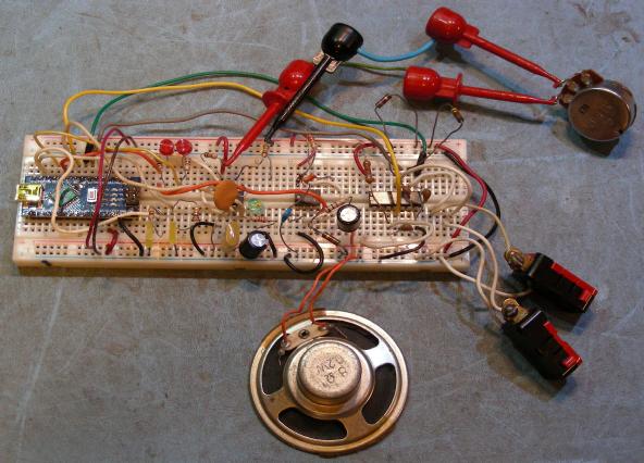
SibKeyerQSK with blinky LEDs, initial build on a plug board
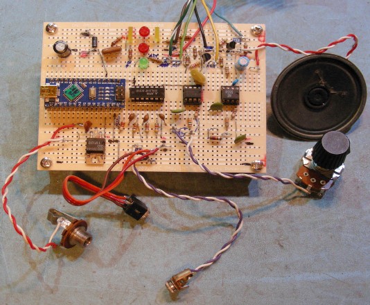
SibKeyerQSK with blinky LEDs on a OnePas OP1210B solder board
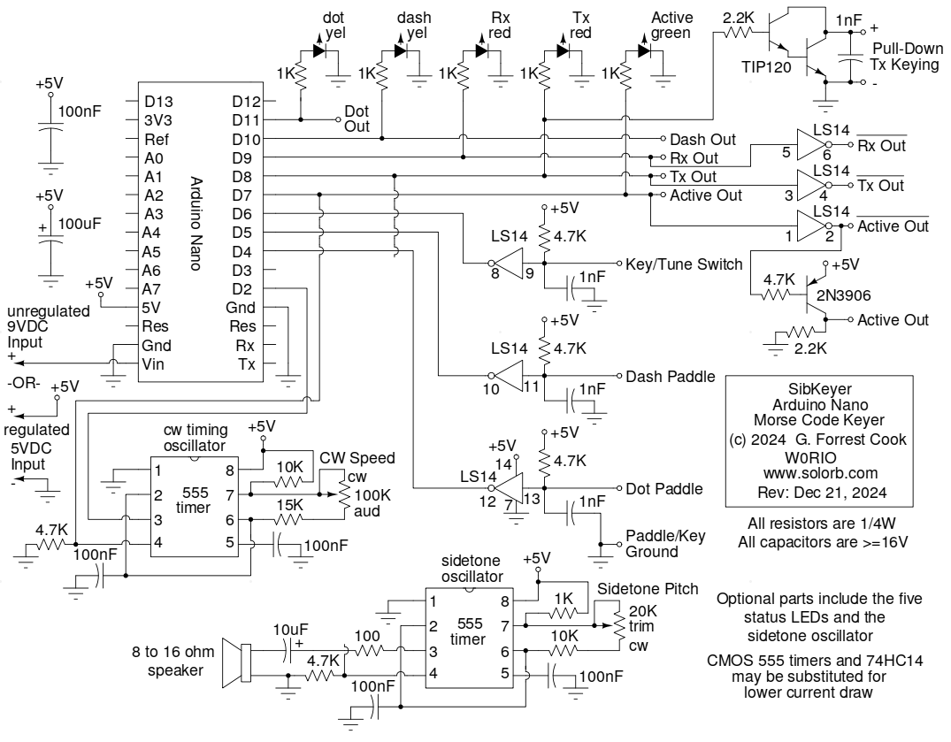
Schematic of the SibKeyerQSK circuit with optional features
The Dot, Dash and Rx status LEDs as well as the !Rx Out and !FSCW Out buffers can all be eliminated if you are building the simpler non-QSK version of the keyer. The Tx and Active LEDs and sidetone oscillator are optional for either version. The !FSCW Out buffer is only needed if the builder wants to experiment with two-tone CW. The Smooth Tone Clickless CW Sidetone Generator would be a nice addition to either version of the SibKeyer.
Back to FC's Ham Radio Circuits page.