(C) 2012-2024, G. Forrest Cook
These two low voltage linear power supplies can power a variety DC devices. The output voltage is kept steady with an adjustable regulator circuit. It features a switch-selectable fixed 13.5V output and an adjustable 1.25V to 17.0V output on the first (silver) version and 1.25 to 22.0V on the second (blue) version. The maximum output current is around 4A at 13.5V, the supply can produce higher intermittant currents.
When set to the fixed 13.5V setting, the supply can provide power for medium-power Ham Radio rigs, VHF radios, CB radios and car stereos. Two older first and second generation power supply schematics are shown below, the new third generation version is recommended for all new builds.
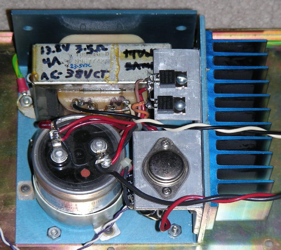
The supply that was built on the blue power supply frame has a much larger heat sink that is shared with both the 2N6052 and the Schottky rectifiers. It can provide a continuous current of 4A at 13.5V and higher currents at low duty cycles. This version of the supply uses the center-tapped transformer and two rectifier diodes shown in the Version 1 schematic. Its unloaded main capacitor voltage is higher at 23.5V so its output voltage can go up to 22V. The silver version of the supply has an unloaded capacitor voltage of 19VDC.
12V 4A Fixed/Adjustable DC power supply build #2

12V 4A Fixed/Adjustable DC power supply build #1 (before completion)
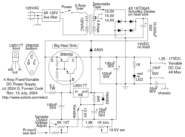
Version 3 schematic for the Fixed/Adjustable DC power supply
This is the new and improved third version of this supply, it is much more rugged and stable than the first two versions.
120VAC power is fed to the supply through an optional IEC plug power line filter. The filter can be helpful for reducing noise from the AC line and is recommended if the supply is to be used with radio equipment. The line power is controled with an SPST toggle switch and a 2 Amp fuse protects the circuitry from overload conditions.
The above photos and schematic show the regulated DC power supply. The second photo shows an earlier version of the supply, a few additional parts have been added including the variable voltage control and fixed/variable selector switch.
In the fixed 13.5V setting, the output voltage is set by the 1K trimmer pot. In the variable setting, the voltage is set by a 5K, 10 turn potentiometer that is mounted on the front panel. The variable output voltage range is from 1.25V to 17V or 1.25V to 22V depending on the transformer and rectifiers that are used. The optional resistor R-maxV can be added if adjusting the pot produces the maximum voltage before the pot is fully turned. The value of R-maxV can be determined experimentally.
The silver version of the power supply uses a single-ended power transformer that feeds a Schottky diode bridge rectifier which converts the AC into pulsating DC. After rectification, the DC power is filtered by a 10,000uF electrolytic capacitor. The supply's maximum output current is limited to 4 Amps by the capabilities of the power transformer. Schottky diodes are not absolutely required, regular silicon diodes will drop more voltage and produce more heat, they will require a slightly higher input voltage to produce the same output voltage.
The power transformer used in the silver version of the supply was a surplus part. Two additional taps were added to the transformer's output winding by winding two turns each of 14 gauge insulated copper wire around the existing transformer windings. The extra windings boost the transformer voltage up by around 1/2 Volt per tap. This increases the maximum regulated voltage that the supply can produce. The 15.5V tap allows the maximum output voltage to go up to 17V, the lower voltage taps can be used if the maximum regulated output voltage is below 17V.
The power transformer in the blue version of the supply has a center-tapped output winding. That feeds a pair of 18TQ045 Schottky diodes which produce pulsating DC. The DC is filtered by a 12,000uF filter capacitor.
The LM317T variable voltage regulator provides the main voltage regulation for the supply. The 2N6052 PNP darlington transistor increases the current handling capacity of the regulator above the 1.5A maximum that the LM317T can provide. The 2N6052 can pass 12A of current continuously and 20A of peak current, it has a nominal gain of 3500 @ 5A. The 5.1 ohm resistor between the emitter and base of the 2N6052 sets the turn-on point for the transistor. The transistor carries the majority of the current and this configuration causes it to follow the regulated LM317T output voltage.
The 10uF tantalum capacitor between the LM317T adjust pin and ground improves the regulator's ripple rejection. The 1N4002 diode prevents a harmful current flow from the 10uF capactior into the LM317T adjust pin if the output pin is grounded. The 6A05 diode protects the LM317T in in case the output terminals are connected to a voltage that is higher than the LM317T input voltage. This can prevent problems if the supply is connected to a battery or a charged capacitor while it is powered off. The 6A05 diode is in parallel with an internal diode in the 2N6052. The LED and 1K current limiting resistor acts as a primitive voltage indicator, it also acts as a small mimimum output load to keep the LM317T happy. An optional analog meter can also be added across the supply, a common 1 milliamp meter with a series current limit/calibration resistor would work.
The 100uF and 100nF capacitors on the output of the regulator provide a capacitive load that prevents spurious oscillations. The 10nF capacitor on the output pins bypasses radio frequency energy that may be picked up by the output wires and the 10nF capacitor between the negative side of the circuit and the AC ground/chassis ground bypasses RF on the DC side of the supply to the AC ground.
Both versions of this project were junk box specials, they were mostly built from surplus parts. new parts were used for the rectifiers and PNP Darlington pass transistors.
The first (silver) build of this power supply was built into an aluminum box, the IEC power connector was mounted on the back of the box. The power switch, fuse, output connectors and variable voltage adjustment pot were mounted on the front. Note that the photo shows the box before the adjustment pot and selector switch were added. The DB-25S connector is used as an output connector, groups of pins were connected in parallel for more current handling capacity. The heat sink in this build is the limiting factor for the maximum continuous current, a larger heat sink is recommended.
The second (blue) build of this power supply was constructed on the chassis of a Standard Power Supplies model SPS40-12 which had a defective regulator circuit board. The chassis, heat sink, power transformer and 12,000 uF capacitor were all were salvaged from the original device, everything else was removed. The power supply chassis was mounted in a metal box. The AC input connector, AC fuse, power switch, DC output terminals and chassis ground connection were mounted on the outside of the metal box.
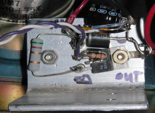
12V 4 Amp regulator wiring below the 2N6052 transistor, the 10uF cap was added later
The regulator assembly in both builds was wired in a point-to-point fashion on the back side of the 2N6052 transistor's heat sink. The 2N6052 case is electrically hot and should be isolated from the chassis with mica washers or grey isolation pads. Be sure to use silicone grease between the transistor and the heat sink. The LM317T regulator was attached to the 2N6052 collector mounting screws, this provides both an electrical connection and a thermal connection so that the LM317T can sense the temperature of the transistor.
Note that the LM338K IC used in the version 2 circuit is now considered an obsolete part and prices have gone up while availability has gone down. The LM338K is also a very fragile part and is more suited for use in applications that have a fixed load resistance. The LM338K is not recommended for a variable voltage bench supply. Shorting the output of the supply will destroy the LM338K. This includes connecting the output directly to a lead-acid battery that is discharged to zero volts.
Version 1 of the supply is similar to the new version 3 circuit. In Version 1, a lower current LM317L adjustable regulator was used instead of the LM317T and the 2N6052 base to emitter resistor was 150 ohms, this has been reduced to 5.1 ohms in the new version.
Back to FC's Ham Radio Circuits page.