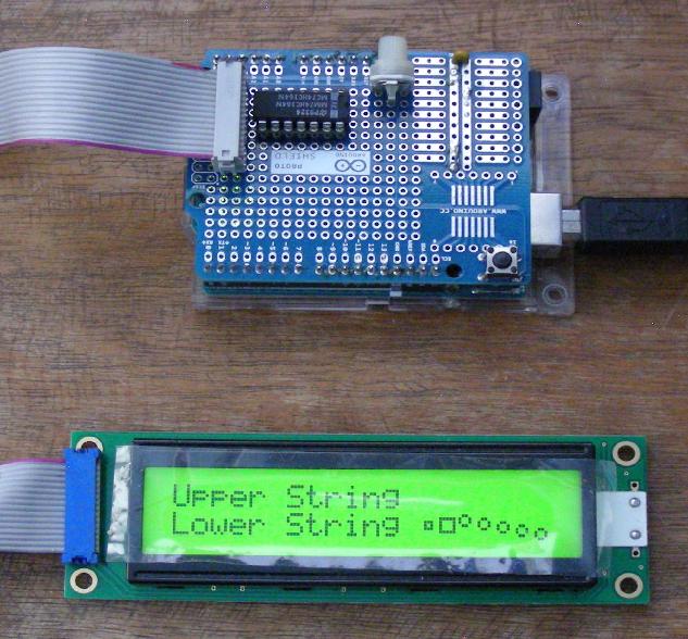
Arduino LCD interface showing custom characters
(C) 2024, G. Forrest Cook W0RIO
Arduino LCD interface showing custom characters
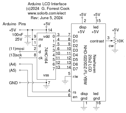
Arduino LCD interface schematic
This project uses an Arduino Uno microcontroller board to drive a Newhaven 20x2 line liquid crystal display (LCD) board. A second version of the Arduino code which supports a Fema 20x4 LCD is also available. A variety of useful utility functions have been included in the Arduino sketch to run the display through its paces. Each of the functions run for a few seconds, then cycles to the next function in a round-robbin fashion.
The code can be used as the starting point for many Arduino-based projects that use an LCD, unused functions and data can be commented out to save memory for other software. With minor changes, the code can be used on any LCD that has a Hitachi HD44770 compatible controller, which is a widely used standard.
Functions are included for displaying characters and strings on the display at specified locations. A scrolling function can be used to display a stream of characters across multiple lines on the LCD. Examples are included for scrolling a canned message as well as scrolling input from the Arduino's USB serial port.
Numeric functions support the display of signed multi-digit integer numbers and hexadecimal numbers with 2 or 4 digits.
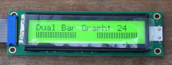
Arduino LCD interface showing integer count and dual bargraphs
Two LCD bargraph functions use custom characters to build either a Left to Right or Right to Left 24 step bargraph using 8 character cells. Each character cell can have 0, 1, 2 or 3 bars, the bars are spaced so they are spread out evenly across multiple character spaces. This can be used to display a variety of data such as a timer state or an analog input. With some minor code changes, the bargraph can be expanded to support more character cells and steps.
A simple animation example produces an expanding square in one character cell. A bouncing ball animation with simulated gravity produces simulated movement across a number of character cells. The animations can be used to display timing events or can just be used as fun eye candy. Both animations use custom characters which can be easily customized to produce other patterns.
A serial input function receives characters from the serial port via the Arduino's USB converter and displays the input as a scrolling display until the enter key is pressed (newline). If no input has been received for a specified number of seconds, the function returns.
An Arduino Uno board is used for the project's microcontroller platform. Other Arduino compatible boards should work, altough this has not been tried.
A 74HC164 serial to parallel shift register is connected to two of the four Arduino SPI pins. The eight output bits from the 74HC164 are connected to the parallel inputs on the LCD board. Note that the SPI clock pin is shared with the yellow LED on the Arduino board, don't try to blink the LED when using the SPI. The SPI pins are also connected to the Arduino's 6 pin ICSP header, the LCD should be disconnected if the ICSP is used to download a new bootloader.
The LCD board has power and ground pins for the controller chip and the backlight LED. These are connected to the Arduino ground and +5V lines. The LCD's contrast pin is connected to the wiper of a 10K trimmer pot, the ends of the pot connect to +5V and ground. The LCD's Register Select (RS) pin connects to the Arduino A4 pin. The LCD's Enable (EN) pin connects to the Arduino A5 pin. Other Arduino pins can be used for these control lines with minor changes to the code. The LCD's R/W pin is permanently tied low, only write operations are used.
A generic Arduino-compatible prototype board contains the LCD interface circuitry and the display connector. The 74HC164 shift register was mounted in a socket on the proto board and was hand-wired using wire-wrap wire with soldered connections. A 16 pin dual row male header was soldered to one edge of the proto board. A ribbon cable with an IDC press-on female header connects to the 16 pin male header. The other end of the cable connects to the LCD with a low-profile header that was soldered to the LCD board. Be sure to verify which header pin that LCD pin 1 connects to on the proto board, the pin numbers may flip depending on which side of each header the ribbon cable exits.
Back to FC's Arduino Circuits page.