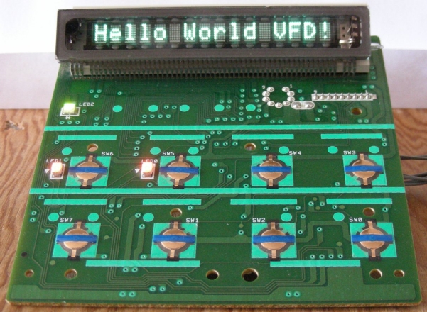
Hewlett Packard U19PB1996-5/16 VFD user interface board
(C) 2025, G. Forrest Cook W0RIO
Hewlett Packard U19PB1996-5/16 VFD user interface board
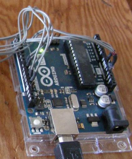
Arduino Uno VFD interface connections
This project involves the reverse engineering of a vacuum fluorescent display (VFD) board from an HP LaserJet 4M Plus printer and connection to an Arduino Uno microcontroller board. A number of useful utility functions have been included in the Arduino sketch to run the display and associated pushbuttons and LEDs. Each of the functions run for a few seconds, then cycles to the next function in a round-robbin fashion. This project is very similar to my Arduino 20x2 LCD experiments and some of the code from that project has been moved over and modified to work with this display.
The code can be used as the starting point for a number of different Arduino-based projects that require the display of ASCII text. The code will also work with any other VFD that uses the Mitsubishi M66004SP controller IC. Unused functions and data can be commented out to save memory.
Functions are included for printing individual characters and strings to the display at specified locations. A scrolling function can be used to display a stream of characters across the VFD.
Numeric functions include the ability to display signed multi-digit integer numbers and hexadecimal numbers with 2 or 4 digits.
Control functions for the VFD include setting underline cursors at arbitrary character locations, changing the display brightness to eight different levels and activating the display test, which turns on all of the pixels. The M66004SP can display the full upper and lower case ASCII character set as well as a secondary character set and up to 16 custom characters. An example custom character is created and displayed by this program.
The HP U19PB1996-5/16 interface board includes eight pushbuttons and three LEDs. The LEDs are attached to a 74HC595 latching shift register IC and the pushbuttons are attached to a 74HC165 parallel input shift register. Both of these ICs are connected to the same SPI control pins on the Arduino board to support simultaneous input and output.
An Arduino Uno board is used for the project's microcontroller platform. Other Arduino compatible boards such as an Arduino Nano should also work.
The VFD board requires +5VDC power and ground connections, these can be connected to the Arduino board, which gets its power from the USB connector.
The M66004SP and 74HC595 share the Arduino's SPI clock and MOSI (serial data output) line. The 74HC165 uses the same SPI clock and MISO (serial input) line. The M66004SP load data bin is connected to the Arduino's Digital 9 pin. The 74HC595 and 74HC165 are both connected to the Arduino's Digital 8 pin for shared latching and loading operations. See the source code file for the interface wiring details.
Two pin headers were connected to the nine wires coming from the VFD board, these plug into the Arduino sockets. The 5V and ground lines are attached to a 3 pin male header. The five interface wires are attached to an 8 pin male header which plugs into the Arduino's digital 8 through 13 pins with three unused connections. Be careful to get the pins plugged into the correct Arduino socket pins before applying power.
Back to FC's Arduino Circuits page.