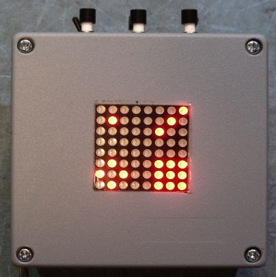
Domino Clock Front View displaying 13:09 in 24-hour mode
(C) 2025, G. Forrest Cook W0RIO
Domino Clock Front View displaying 13:09 in 24-hour mode
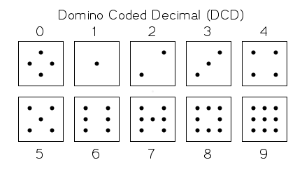
Domino Coded Decimal Digits 0-9
This project uses an 8x8 red LED array and an Arduino Nano microcontroller to make an unusual clock which displays time as four domino-style digits. A Dallas DS3231 real-time clock module is used for keeping accurate time and a MAX7219-based 8x8 LED module is used for the display. Both of these modules are available online for relatively low prices.
The clock's hour is displayed as two digits on the upper part of the display, the minutes are displayed as two digits on the lower part of the display. Reading the Domino Clock takes a small amount of training. After you observe the clock for a few days, it becomes as easy to read as a conventional digital clock.
Controls include time set pushbuttons for Hours, Minutes and Zero Seconds. A fourth pushbutton is used to cycle the display brightness up and down. Two toggle switches are used to select the 12/24 hour mode and to turn the animation features on and off. Animation feaures include a moving seconds dot and a random bit pattern that briefly flashes over the entire display at the beginning of each new hour. The seconds animation dot moves back and forth in a zig-zag pattern across the middle of the display.
The clock is powered by 5VDC power, which can come from a common USB power supply. If an optional LM2596 DC to DC converter module is added, the clock can be powered from 9-16VDC, making it compatible with 12V automotive power sources and DC solar power systems. The clock's current draw is between 20mA and 100mA at 12.8VDC using the LM2596 module depending on the brightness setting and displayed digits.
An Arduino Nano board is used for the project's microcontroller platform. Other Arduino compatible boards such as an Arduino Uno can also be used.
The Arduino and outboard modules all connect to common +5V and ground busses, which are supplied by the output of the DC-DC converter board. If the clock is to be powered by the Arduino's USB socket, the modules are powered from the Arduino's external +5V and ground pins.
The MAX7219 display module connects to the Arduino SPI port, (11)(MOSI) & (13)(SCK). The MAX7219 !load pulse is connected to digital 9 on the Arduino.
A Dallas DS3231 real-time clock chip is connected to the Arduino I2C bus on pins a4 and a5. The 12 or 24 hour mode is selected by a switch on digital 4. The seconds animation mode is activated by a switch on digital 5. Time and the brightness level are set via four pushbuttons on digital 6, 7 and 8 and 3. The switch inputs are all pulled up to +5V through internal resistors on the Arduino and are grounded when the switches and buttons are activated.
The Domino clock was built into a Twin Industries G20-7100 gray plastic box with dimensions of 3-1/2"x3-1/2"x2-1/4". A square hole was cut into the front side of the box to hold the LED matrix. The hole was started by marking the dimensions on the box with a Sharpie pen then drilling small holes inside of the marked area. The hole was then carefully enlarged to the final size with a file. Six holes were drilled into the top of the box to hold the time set buttons, the brightness button and the two mode switches. One hole was drilled into the rear of the box for the DC power wire.
All of the circuitry is contained in the various small PCB modules. Modules include the Arduino, the real-time clock, the 8x8 LED display, and the optional DC-DC converter. Most of the modules have their connections brought out to 0.1 inch header pins, the various pins are connected together using 0.1 inch female headers. The DC-DC converter is connected via wires that are soldered into the board.
Back to FC's Arduino Circuits page.