(C) 2011-2023, G. Forrest Cook
This project involves the construction of a low-cost curve tracer that is suitable for testing a wide variety of electronic components both in-circuit and out-of-circuit. It is easy to construct and is very useful for finding defective semiconductors and other components when troubleshooting electronic devices. The octopus is a circuit that has been around since at least the 1960s, it gets its name from the numerous wires that come out of its box.
The octopus is used in conjuction with an oscilloscope that is set to display in X-Y mode, the scope needs to have a horizontal (X) input. The circuit displays voltage across the test probes on one axis and current through the probes on the other axis. The octopus can be thought of as a curve tracer with a vector graphics display format, the trace always returns to its starting point.
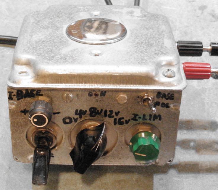
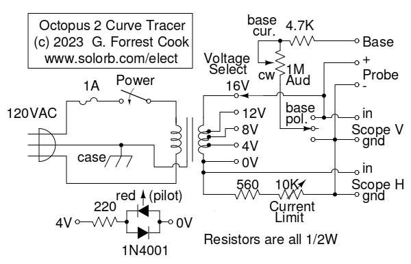
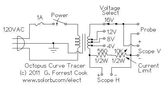
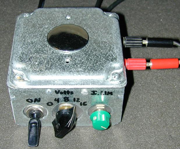
Compared to the classical octopus circuit, this version features a tapped low-voltage transformer for selecting a variety of test voltages as well as an adjustable current-limit potentiometer for selecting the test current range. The latest (2013) version the octopus adds a third probe connection for attaching to the base or gate terminal of transistors. A base polarity switch with a center-off position and an adjustable base current control were added to the box along with a third probe jack. An LED pilot light is also included in the new circuit. Here is the original circuit and a photo of the original box for comparison.
Power is applied to the step-down transformer through a 1 amp fuse and a power switch. The transformer has output taps at 4V, 8V, 12V and 16V. The voltage select switch allows one of four voltages to be selected. If you can't find an equivalent transformer, a common 12.6VAC center-tapped filament transformer will provide two voltages or a 10VAC doorbell transformer or 6.3VAC filament transformer will work if only one voltage is desired. The series resistor on the pilot light circuit should be increased in value if it is run on voltages above 4VAC.
The current limit variable resistor selects the peak current that can go through the test probes, the 560 ohm resistor sets the maximum current. When the probes are open, the scope will display a vertical line, when the scope probes are shorted, the scope will display a horizontal line. The octopus places a constantly changing sine wave voltage and current across the probed device. The horizontal axis shows the current through the probes and the vertical axis shows the voltage across the probes. As the sine wave changes, the scope trace loops around in accordance with the associated current and voltage readings from the probe. Probing different electronic components will produce a variety of unique patterns on the scope.
When testing transistors, the two main probes are connected to the transistor's emitter and collector leads and the base probe is connected to the transistor's base lead. Varying the base current control will cause the scope waveform to change, indicating the transistor's ability to amplify. The base current potentiometer is shown as a common 1M audio-taper part in the schematic. Current is increased as the pot is turned to the left. A log-taper potentiometer can be wired the opposite way for more current in the clockwise setting. A linear potentiometer will also work, but the range will be more compressed towards the higher current settings.
The octopus was built into a 4"x4"x2" electrical utility box as shown in the photo. A tall lid was used for the top of the box to make enough room for the transformer. The box knock-outs on the front were removed and the switches and potentiometers were mounted on an aluminum plate that was screwed into the side of the utility box.
The test-jack holes were drilled directly into the box and the power and oscilloscope cables were secured to the box with Romex cable clamps. The oscilloscope cables were made with flexible RG-58 coaxial wire and were terminated with BNC connectors for direct connection to the scope inputs.
Connect the Horizontal and Vertical connectors to the oscilloscope inputs. Adjust the Octopus transformer voltage taps and current limit control. The 8V tap with the current limit set to mid-way is a good place to start. Adjust the scope's vertical and horizontal amplifiers for full screen-width lines when the two main probes are open and shorted.
The vertical and horizontal inputs can be exchanged if you prefer, this will cause the displayed pattern to rotate by 90 degrees. Place various components across the main test probes and observe the resulting display. A silicon diode is a good component to start with, it will verify that the Octopus is functioning normally by displaying an L-shaped curve.
Here are some typical curves that the octopus will display using the normal two probe test:
The octopus is especially good at finding defective semiconductor devices. Power transistors and diodes often short out when they fail. The octopus can quickly find shorted parts, even in-circuit. Leaky transistors and diodes will have curves with rounded corners and/or angle patterns that are wider than 90 degree (right) angles.
Older germanium transistors will display a different set of patterns when compared to modern transistors. Keep in mind that antique germanium transistors also tend to show as leaky, even when they are perfectly good devices.
For a more complete test of a bipolar transistor, place the main probes on the transistor's emitter and collector leads and connect the base probe to the the transistor's base lead. Adjust the base current potentiometer and observe the waveform change from a line with a small blip on one end to an L-shaped diode curve. If the base polarity switch is flipped, one polarity of base current will cause the display to show a wider range of control on one or the other polarities. If the base polarity switch is set to the center-off position, no base current will flow and the transistor should show the fully-off EC pattern. Low-gain (low-beta) power transistors will be less sensitive to the base current control when compared to high-gain small-signal transistors.
NPN and PNP transistors will show a much wider range of base control with the base polarity switch set to one or the other polarity. The forward-biased setting will produce a line with a variable but sharp angle and the reversed-biased setting will produced a line with a variable curved end. To discover whether an unknown transistor is an NPN or PNP device, compare the patterns to a known transistor type such as generic 2N3904 NPN and 2N3906 PNP transistors. Comparison to known parts is also a good way to discover which leads on unknown transistors are the emitter, base and collector.
MOSFET transistors can be tested with 3 leads, the main probes should be connected to the transistor's source and drain leads and the base probe should be connected to the transistor's gate lead. The MOSFET pattern will show a squared Z-shape curve with the gate bias off or low, one end of the pattern will open up as the bias is increased. Since MOSFET gate terminals are very high-impedance, the base polarity switch may need to be moved between the on polarity and the center-off posititon to observe the operation of the transistor in the fullly off condition.
In-circuit testing with the octopus is a bit of an acquired skill, a wide variety of curves with complex shapes can be observed. Faulty components can often be identified in-circuit, especially when they are shorted out. If suspicious components are found, they can be removed from the circuit and tested in a stand-alone manner.
Back to FC's Test Equipment Circuits page.