|
|
|
|
|

(C) 2013, G. Forrest Cook
The WGR1 circuit is used to regulate the charging of a lead acid battery system from a DC-output wind generator. It consumes minimal power when idle and efficiently delivers charging power to the battery when the wind generator is up to speed. Excess charging power is diverted to a large dump load resistor, the heat produced can be used to keep the battery warm when used in cold climates. The WGR1 circuit can be used in conjunction with a photovoltaic (solar) charge controller such as my SCC3 design.
The WGR1 circuit features make-before-break switching. This ensures that the current from the wind generator is either going to the battery, to the load, or very briefly to both during the transition time. By managing the switching this way, high voltage transients are minimized, protecting the MOSFET transistors. The make-before-break switching also guarantees that there will always be a load on the wind generator. Unloaded wind generators tend to spin out of control and may even self-destruct.
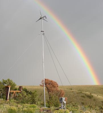
This project came about after my 400W Southwest Windpower air-X wind generator was exposed to winds in excess of 120Mph (above the unit's maximum rated wind speed), which caused the internal control electronics to burn out. The air-X internal regulator was replaced with a set of six high-current schottky diodes wired in a standard 3-phase bridge rectifier configuration. An electrolytic capacitor with a rating of 5000uF at 63V was placed across the rectified DC output of the wind generator at the base of the tower. The capacitor smooths out the pulsating DC power from the bridge rectifier. The DC power from the wind generator is fed to the WGR1 regulator circuit via heavy-duty copper wiring.
12VDC (nominal) operating power is supplied to the WGR1 circuitry from the 12VDC battery that the system charges. The 12VDC is regulated to 5VDC via a 78L05 regulator IC, this powers the logic circuitry. The voltage doubler circuitry is driven by two opposite polarity square waves that are produced by one flip-flop in a 4013 CMOS IC. The Q! signal drives a 2N3904 transistor that pulls the doubler input to ground. The Q signal drives the 2N3904 and 2N3906 transistors to pull the doubler input to +Vbat (12VDC). The output of the doubler is around 23VDC, it is used for driving the "Wind2Bat" MOSFET array.
The gate drive circuitry for the "Wind2Bat" MOSFET array uses a 4N35 opto-isolator to pull the gate of the MOSFETs up to 23V for the "on" state and a two transistor level shifter to pull the gate down to 5V (negative 8V relative to the MOSFET source pin) for the "off" state. Driving the gate voltage negative insures that the MOSFET array turns off completely.
Half of a TLC2272 op-amp is wired as the 3Khz master clock oscillator. The output of the oscillator is sent to a 4040 CMOS divider IC which produces a selectable variety of slower square waves. The switching rate can be chosen by a 5-position DIP switch, the rate can be optimized for a particular wind generator. The 3Khz oscillator also feeds half of a CMOS 4013 flip-flop to produce the waves that drive the voltage doubler circuit.
The battery voltage comparator and equalization circuitry is derived from my SCC3 charge controller design. Half of a TLC2272 op-amp is wired as a voltage comparator circuit, it compares a scaled version of the battery voltage to an approximately 2.5V reference voltage. The output of the TLC2272 op-amp (pin 1) goes low when the battery voltage is above the float setpoint and high when the battery voltage is below the float setpoint. The temperature compensation circuit is used to raise the float setpoint when the battery is cold. The equalization switch can be turned on to raise the float setpoint by an adjustable amount, this allows for occasional overcharging (equalization) of the battery.
The battery comparator output is sent to a 4013 flip-flop chopper stage where it is gated by the low-speed system clock. This limits the rate at which the controller can switch between accepting wind power and dumping wind power. The output of the chopper stage is sent to the make-before-break timing and logic circuit.
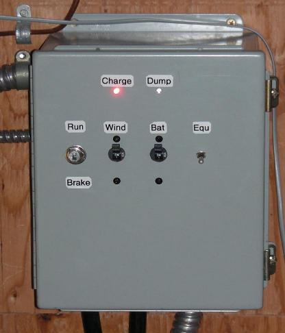
The make-before-break circuitry was borrowed from my All-Ears QSK Timing Generator, a ham radio timing device. It produces the overlapping Wind2Load and Wind2Bat signals that are used to control the power switching MOSFET transistors. The outputs from this part of the circuit are also used to light the Accept Wind and Dump Wind status LEDs. Note that the Accept Wind LED is labeled "Charge" on the above photos.
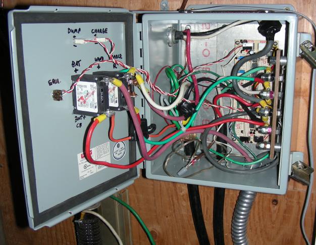
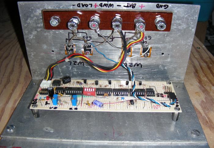
The WGR1 circuit was separated into two sections, both sections are installed in a heavy-duty electrical junction box. The first section is a logic board with most of the low power circuitry. The second section includes all of the high current wiring and the power switching MOSFET transistors. A heavy-duty 5-pin terminal strip was constructed with a piece of 1/4" thick bakelite insulator an 1/4-20 screws, nuts and washers. This provides a solid connection point for all of the heavy gauge wires that are used in the circuit. A pair of 30 Amp Airpax ALM series DC-rated circuit breakers were used as over-current protection devices for the battery and wind generator positive circuit legs. An automotive SPDT switch was originally used for the wind generator brake control, this was a low-quality pot metal switch that eventually broke and was replaced with a heavy-duty knife switch.
The external wiring from the wind generator uses inflexible 8 gauge house wiring. These wires were bonded to more flexible connecting wires using electrical compression connections, this allows the door of the box to open and close more easily. The ends of the all of the heavy wires were crimped and soldered to 1/4" lug terminals, these connect to the terminal strip, circuit breakers and brake switch.
It takes a fair amount of metal work to construct this project. A number of holes were cut into the metal box using Greenlee hole punches, the punches should be sized for 1/2" and 3/4" standard electrical cable clamps. The MOSFET transistors were mounted to a large aluminum heat sink sheet that was screwed into the standoffs on the back of the metal box. The transistors were mounted with insulating hardware to prevent contact with the grounded aluminum heat sink. There are four MOSFET transistors, they are wired in parallel to make two arrays. Be sure to use heavy gauge wiring for the drain and source lines.
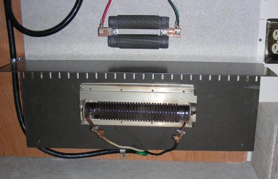
The wiring to the brake and dump load resistors uses surplus electric dryer cables with the plugs removed, any suitably flexible wire with enough current capacity will work. In cold climates, both resistors can be mounted near the battery storage compartment to keep the batteries warm. Warming the batteries can significantly increase the amount of energy that can be delivered. The resistors, especially the brake resistor, can get extremely hot in high wind conditions, even to the point of glowing red. The resistors should be kept far from any flammable materials. The resistor bank should be mounted on a metal frame that is surrounded with metal screens. A fireproof backing can be made with concrete backer-board or cinder blocks.
The current from a wind generator is proportional to a cubic function of wind speed, charging current tends to come in the form of short-duration spikes that coincide with wind gusts. The maximum current from the generator is limited by the generator magnets, coil saturation and feed wire resistance.
Most of the smaller electronic parts can be obtained from electronic supply houses such as Jameco, Mouser and Digi-Key. The DC-rated circuit breakers and power resistors are often available on eBay for reasonable prices. The Run/Stop switch can be purchased at automotive parts stores and the metal box can be purchased from electrical supply houses or big-box hardware stores.
There are two things that need to be adjusted to optimize the WGR1 to your particular wind generator and battery components, the setting of the Chopper Rate Select switch and the value of the dump load resistor. The 23 Hz chopper rate was found to produce the most stable operation with the modified Air-X wind generator. Monitoring the instantaneous wind generator current is quite difficult with a current meter or an oscilloscope wired to measure charging current. This is due to the very random nature of the wind, the rising and falling DC voltage and the chopping action of the regulator circuitry.
A useful trick for monitoring the "accept" and "dump" currents is to wire a small 8 ohm loud speaker across two distant points on the negative power lead coming from the wind generator, this allows you to hear the current signal. A small wire was tapped into the wind generator feed line about 50 feet from the WGR1. That was routed to one side of the speaker and the other side of the speaker was connected to the same wire at the WGR1 box. There is enough resistance in the feed line that the current through it develops a voltage that can drive the speaker. The speaker allows one to listen to the sound of the pulsating DC current coming from the wind generator.
When the WGR1 switches between "Accept Wind" and "Dump Wind", the current in the wind generator supply lines should be set for minimal change, this is done by adjusting the value of the dump load resistor. The dump load resistor adjustment should be performed when the wind is blowing hard, the battery is full and the WGR1 is switching between the accept and dump states. If the WGR1 is used in parallel with a solar charge controller, disconnect the solar power when performing this test.
A set of eight 6.8 Ohm, 200 Watt power resistors was used for tuning the dump load resistance. The resistor leads should all be short and made with heavy copper wire. At least one resistor should always be connected during this test. The dump load resistance drops each time another resistor is added in parallel. As the resisistance was decreased, the sound from the current monitoring speaker reduced, then got louder again as the resistance was further lowered.
With the modified Air-X wind generator, four 6.8 Ohm, 200 Watt resistors wired in parallel as a 1.7 Ohm 800 Watt resistor provided the quietest switching signal on the current monitoring speaker under high winds. Note that the optimum resistance may result in a louder signal on the speaker when the wind is blowing at a medium rate, the switching noise should only be minimized at the highest wind speeds.
Due to the intermittant nature of wind, it may be necessary to get all of the components used in this test ready to go, then wait for a windy day to do the final adjustments.
Operation is straightforward, just flip on the two circuit breakers and put the Run/Brake switch in the Run position. The amber Accept Wind LED (marked "charge" in the above photo) will stay on whether the wind is blowing or not. Battery charging will happen as soon as the wind generator's output voltage rises above the battery voltage. When the battery charges up to the float voltage during windy conditions, the Accept Wind and Dump Wind LEDs will blink alternately and the dump resistor bank will start to generate heat.
Keep in mind that the wind generator may spin too slowly to produce any charging current, the wind generator's voltage must be higher than the battery voltage for charging to take place. In light to medium winds, the generator's speed tends to stabilize at the point where the battery is taking a light charge.
If your battery needs equalization, turn on the Equ. switch for a while, equalization will only take place if there is sufficient wind to produce a charging current. When the Accept Wind/Dump Wind LEDs start to alternate, the battery has reached the equalization setpoint.
If you need to service your wind generator or disable wind charging while you are away from your system, set the Run/Brake switch to the Brake position and shut off both circuit breakers. Placing a temporary shorting jumper across the 1 ohm brake resistor may help to further reduce the speed of the wind generator.
Unlike the original Air-X regulator, this circuit has survived many days of operation in extreme wind conditions. The generator produces currents in excess of 20 amps while the wind generator blades make howling and screaming noises. During these wind conditions, the MOSFET transistors remain cool to the touch and the dump load resistor bank becomes quite warm.
Back to FC's Solar Circuits page.