For higher power solar systems, see the CirKits solar charge controller circuit board kits.
(C) 2001 G. Forrest Cook
Are you tired of always spending money on flashlight batteries only to have them fail just when you really need them? Try this simple circuit out. The white LEDs are quite bright and produce a tightly focused beam. The LED array can provide enough light to illuminate a small work area or reading area at night. The red, orange, yellow and green LEDs broaden the lamp's color spectrum to produce a slighly warmer color temperature. This project would make an excellent science fair project.
The box also doubles as a 12V power source and can run other small loads such as a 12V transistor radio. This project was built with the Simpler is Better approach, the materials are common and many substitutions are possible.
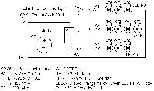
Operating Voltage: 11-13.8V DC
Solar Charging Current: 60ma approx.
LED Lamp Operating Current: 60ma approx.
The solar panel puts out about 60ma of current, this is enough to float-charge the 12V gell cell without overcharging. With this limited amount of charging current, a charge controller is not required. Other batteries may be used such as smaller lead acid batteries or NiMH cells (use 10 in series), but overcharging and leaking battery goo may result if you exceed the battery's charge current ratings. A smaller and lighter 3.5 Amp Hour 12V lead acid battery has been successfully used in a different version of this circuit.
There are 3 series strings of LEDs in this circuit. The resistors limit the current through each string of LEDs to prevent them from burning up. The white LEDs have a higher voltage drop and only 3 can be used in series with a 12V (11-13V) source. The red/orange/yellow LEDs have a lower voltage drop per diode, so 4 can be wired in series. The colored LEDs are optional, they are used to increase the red side of the color spectrum. When this project was first created, white LEDs were fairly expensive, they are rapidly coming down in price.
It is possible to adapt this basic circuit to work with a lower battery voltage, such as 6V. At 6V, the lamp circuit would need to be changed to one white LED and one resistor per string, and a set of red/yellow LEDs and one resistor per string. The resistor values would need to be changed to maintain a 20-25ma current through each LED at the full battery voltage. A lower voltage solar panel could be used to charge the 6V battery, a 7.2V (open circuit voltage) panel would be a good fit.
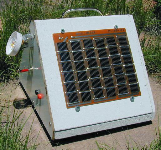
Most of the effort in building this project went into construction of the box. Any shape will do, this unit was built so that the battery just fits inside and the solar panel could is mounted at approximately 45 degrees from horizontal. Particle board and wood screws were used to hold the box together, other materials could be used if the project needs to be used in wet conditions. White gloss spray paint was applied to the particle board to give the box minimal moisture protection and keep it cool in the sun.
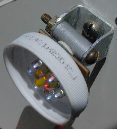
The LED mounting system is somewhat fragile but allows the light to be rotated up and down. The rotating mount cylinder is made from an unthreaded aluminum spacer with a 4-40 screw hole drilled and tapped into the side as a mounting point for the LED circuit board. The cylinder is held in place with a C-shaped aluminum holder, the holder was fashioned from flat metal that was bent in a vise, hammered into shape, trimmed with a pair of tin snips, and filed smooth. The LED circuit board is mounted behind a white plastic water bottle cap which shields the light from the side of the LEDs.
The LED circuit board was custom built with press-n-peel film, it can also be built with a piece of perforated board or prototype PCB material using point-to-point wiring. The resistors are mounted on the circuit board along with the LEDs. Be careful not to overheat the LEDs when soldering, LEDs can easily be destroyed by overheating. A clip-on heat sink is recommended during soldering.
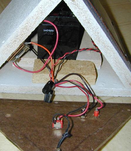
All wiring was done with stranded #22 gauge wire and wire nuts. Note that the specified solar panel comes with its own built in 1N4001 diode, that will work, but a 1N5818 schottky diode in parallel with the existing diode will produce a smaller voltage drop and allow the circuit to charge the battery in lower light.
Turn off the LED switch and point the solar panel at the sun in the morning, adjust the panel towards the sun a few times a day, or simply point the panel in the direction of the sun at noon. The battery will charge. Turn the light on at night, it should be able to produce light through the night. The box will maintain a charge if it is left in a sunny spot indoors. One full day of charging should be enough for several nights of light.
The pin jacks can be used to occasionally check the battery voltage. Under sunlight the voltage may rise to over 13V and at night, it should not be allowed to go below 11V or the battery life will be shortened. A new, fully charged battery will run the light for many hours, so if you put the box in the sun during the day, total discharge should not be a big problem.
Experimenters will want to measure the current in and out of the battery, this can be done by inserting an ammeter in series with the fuse and the battery. Other 12V loads can be powered by this system, just plug them into the pin jacks or better, add a polarized output connector.
This lamp was used regularly for over 10 years, the gell-cell battery eventually dried out and required replacement.
1x 12V 7AH sealed lead acid battery, Panasonic LC-R127R2P or Yuasa NP7-12
1x GM-684 12V 60ma solar panel, p/n 08SLC09 from Elecronix Express
1x red LED, T1-3/4 size
1x orange LED, T1-3/4 size
1x yellow LED, T1-3/4 size
1x green LED, T1-3/4 size
6x white LEDs, T1-3/4 size from Jameco
2x 120 ohm 1/4 W resistors
1x 220 ohm 1/4 W resistor
1x 1/2 Amp 28VDC fuse
1x fuse holder
2x crimp on battery clips
3x wire nuts
1x 1N5818 diode
1x spst toggle switch
2x pin jacks
1x box large enough to fit the battery and solar panel.
   misc hardware
Electronix Express 1-800-972-2225 http://www.elexp.com/
See my
Solar Powered Reading Lamp project for a more advanced portable
solar lamp circuit.
Back
to FC's LED Circuits page.