A kit for the standard 20 Amp SCC3 circuit board used in this project is available from CirKits.
(C) 2012, G. Forrest Cook
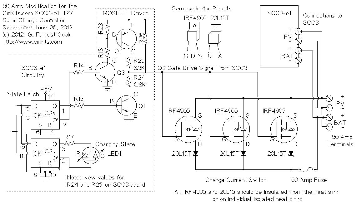
This article describes modifications that can be made to the 12V, 20 Amp SCC3 solar charge controller to allow operation at up to 60 Amps. Similar modifications can be performed to achieve a maximum operating current of 40 Amps (2 sets of IRF4905 MOSFETs and VS-20TQ045-M3 diodes) or 80 Amps (4 sets of IRF4905 MOSFETs and VS-20TQ045-M3 diodes). This article describes the modification for 60 Amps. Note that the 20L15T Schottky diodes are now an obsolete part, Vishay VS-20TQ045-M3 diodes are a suitable replacement.
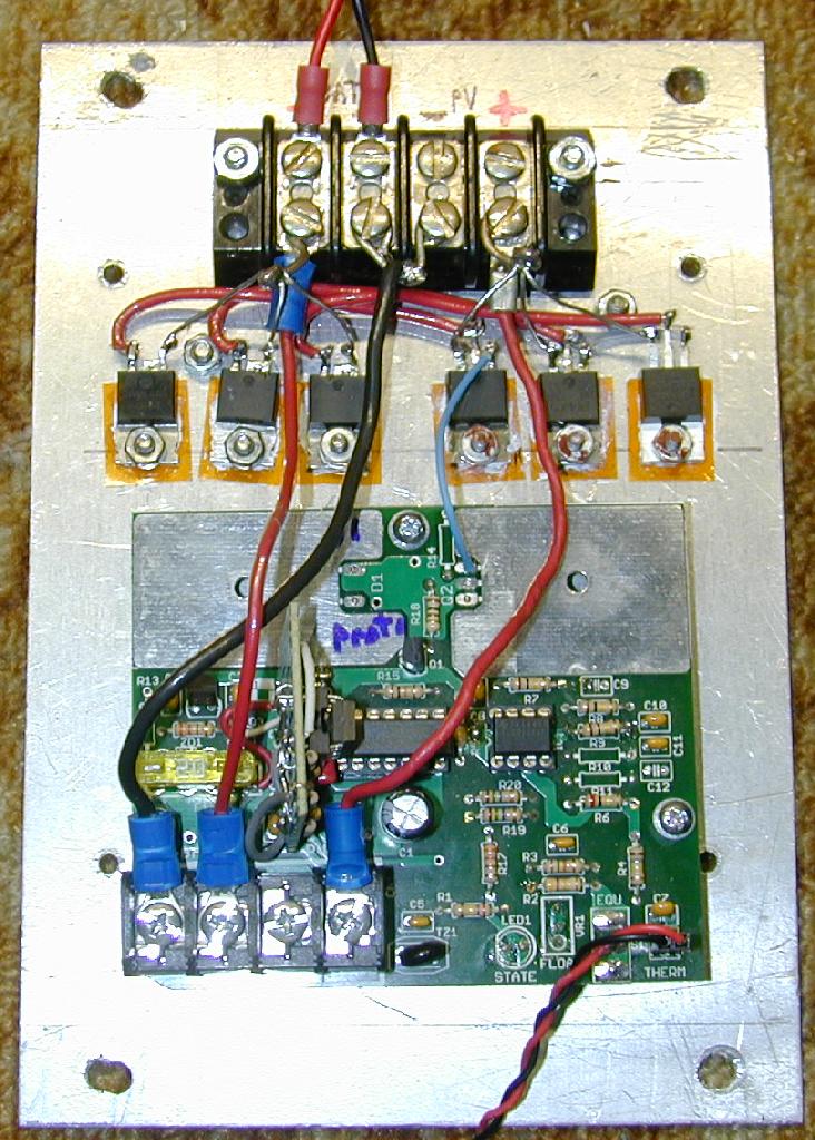
This information pertains to the SCC3-e1 kit (current production version). Note that the SCC3 board in the above photo is an older version of the SCC3 kit, a small vertical circuit board has been added to bring the older circuit up to the SCC3-e1 revision.
These modifications should be performed by someone with a fair level of electronics skills, they involve tracing signals on a circuit board, detailed soldering work and mechanical work. The high currents involved in this project can cause risk of burns and fire hazards. Protective over-current devices (switches and fuses or circuit breakers) should always be used on the PV and battery wiring.
This circuit has been field-tested for many years in an off-grid house, it will work reliably if it is built correctly.
A few minor changes need to be made to the SCC3-e1 circuit board. The charge current switch components Q2 and D1 should be left off of the SCC3 board. If you are modifying an assembled SCC3-e1 board, it is best to just clip the IRF4905 and 20L15T diode leads where they meet the board and add new external parts.
Resistors R24 and R25 on the SCC3-e1 board should be changed to new values. R24 should be 6.8K and R25 should be 3.3K. These two resistors work in conjuction with the capacitance of the MOSFET gates to lower the frequency response of the gate drive signal, that greatly reduces the amount of radio frequency emissions created when switching the high current power lines on and off.
If you build this modification for 40 amps, R24 should be 10K and R25 should be 4.7K. If you build this modification for 80 amps, R24 should be 4.7K and R25 should be 2.2K. It may be easier to parallel other resistors on top of R24 and R25 to achieve the desired resistance, removing soldered parts from a circuit board can be difficult. The parallel resistance values don't have to be exact.
When running the modified SCC3 at higher currents, it is important to mount the SCC3 thermistor in thermal contact with the battery. This wiring is is visible in the photo as a red/black twisted pair. A 2 pin connector and matching header were used to allow easy removal of the thermistor wires.
Three pairs of IRF4905 MOSFET transistors and VS-20TQ045-M3 Schottky diodes need to be installed on a large aluminum heat sink. These parts should be insulated from the aluminum heat sink by using thermally conductive insulators (amber rectangles in the photo) and plastic shoulder washers. Heat sink grease should be used on both sides of the insulators to insure good heat transfer. Before wiring these parts, check the electrical continuity between the screw tabs and the heat sink and fix any shorts.
Note that the transistor and diode mounting screws are electrically live, it is a good idea to cover them with an insulated block on their back side to prevent the possibility of a short-circuit should they come in contact with metal objects. Another approach is to mount the heat sink inside of a larger metal box, be sure to allow sufficient air flow through the box to dissipate the heat.
The three MOSFET/Schottky diode pairs should have equal wire lengths to insure equal current distribution. Note the arrangement in the photo with three diodes, three MOSFETs and equal length red wires. The wiring should be done with heavy wire (12 gauge) to handle the high currents. The three MOSFET gate terminals should be tied together and run back to the original Q2 gate pin (pin 1, blue wire) on the SCC3 board. A heavy-duty terminal block should be used for the external PV and battery connections. These should be connected back to the original SCC3 four-pin connector, light gauge wire is acceptable here since the current to the SCC3 board is now low.
External connections should be made to the heavy-duty terminal block. If you cannot locate a sufficient terminal block, it is possible to build your own using a piece of insulating material such as phenolic block and 1/4-20 threaded bolts. Connections to the bolts should be made with heavy-duty circular crimp lugs, the bolts should be sufficiently tightened and inspected for heating during operation. Soldering the wires into the lugs after crimping is recommended. The insulating block should be mounted to the enclosure with spacers to ensure electrical isolation and physical strength.
The 60 amp fuse in the schematic is not shown in the photo, it has been replaced by a DC-rated circuit breaker that is located in a separate metal box. A second circuit breaker should be installed on the PV + line in the circuit breaker box. Airpax ALM series circuit breakers are a good choice for this application, they are available in a variety of current ratings. If you decide to use fuse and switch combinations instead of circuit breakers, the fuse should be a DC-rated class T type. Class T fuses are filled with sand to prevent internal arcing when they blow.
The wiring from the PV array to the charge controller and from the charge controller to the battery should be done with 6 gauge or larger stranded wire in order to handle the full 60 amps of current. If you will be wiring a system with 45 amps or less, 8 gauge wire may be used. The modified charge controller and circuit breakers should be installed inside of metal boxes and all of the high current wiring should be installed in metal conduit to protect against fire hazards.
The IRF4905 MOSFET transistors and VS-20TQ045-M3 diodes are available from Digi-Key and Mouser Electronics. Airpax ALM series circuit breakers can be found on eBay.
Back to the SCC3 page.