A kit with the circuit board and parts for this circuit is available from CirKits.
(C) 2009-2019, G. Forrest Cook
The SCC3 is a solar charge controller, its function is to regulate the power flowing from a photovoltaic panel into a rechargeable battery. It is easy to set up, using one control for setting the battery float voltage and an equalize switch for occasional overcharging. Automatic temperature compensation optimizes battery charging over a wide range of temperatures. The SCC3 is a robust design, it can handle reverse polarity connection of both the battery and photovoltaic panel.
The design goals of this circuit were efficiency, simplicity, reliability and the use of common parts. The circuit has been designed to be radio-quiet, which makes it suitable for ham radio and short wave listening (SWL) applications. A medium power solar system can be built with the SCC3, a 12V (nominal) solar panel that is rated up to 20 amps, and a lead acid or other rechargeable battery that is rated from 500 milliamp-hours to 400 amp-hours of capacity.
It is important to match the solar panel's current rating to the battery's amp-hour rating (C). A typical maximum battery charging current is C/20, so a 100 amp-hour battery should have a solar panel rating of no greater than 5 amps. If the solar panel output current is below the battery's minimum charging current requirement, the battery may never become fully charged. It is advisable to check the battery manufacturer's data sheets to find the useful range of charging currents, then choose a PV that is a good match for the battery.
Maximum solar charging current: 20 Amps
Nominal battery voltage: 12V
Night time battery current drain: 0.8 - 1.8ma
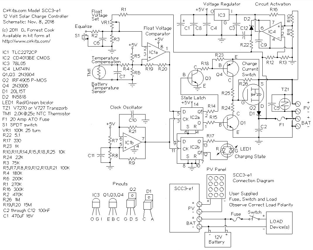
The circuit activation section uses op-amp IC4 wired as a comparator to switch power on for the rest of the SCC3. When the PV voltage is greater than the battery voltage, IC4 turns on and sends power to voltage regulator IC3. Diode D2 prevents damage to IC4 if the battery is connected with reverse polarity. IC3 produces a regulated 5 Volt power source. The 5V is used to power the SCC3 circuitry, it is also used as a reference for the battery float voltage comparator IC1a.
The float voltage comparator IC1a compares the battery voltage (divided by R1/VR1 and R3) to the 5V reference voltage (divided by R5 and R6). The comparison point is offset by the thermistor TM1 for temperature compensation. The comparison point is also modified by the Equalize switch, S1 and R2. The output of IC1a goes high (+5V) when the battery voltage is below the float voltage setting. The output goes low when the battery voltage is above the float voltage setting. This provides the charge/idle signal that controls the rest of the circuit.
The charge/idle signal is sent to IC2a and b, a pair of D-type flip-flops. The flip-flops are clocked by the IC1b phase-shift clock oscillator, which runs at about 150 Hz. The clocking causes the flip-flop outputs to produce a square wave charge/idle signal that is synchronized with the frequency of the clock oscillator. The two halves of IC2 operate in synchronization, IC2a is used to drive the PV current switching circuitry, IC2b is used to drive the charging state indicator LED either red (charging) or green (floating).
The latched charge/idle signals from the IC2a flip-flop switch bipolar transistors Q1 and Q3 on and off alternately. Q1 pulls the gate of MOSFET Q2 to ground, this switches the solar current on through the battery. Q3 pulls the base of Q4 toward ground and Q4 pulls the gate of MOSFET Q2 to the PV+ line, turning Q2 off and stopping the solar charging current.
The solar charging current flows through the heavy lines on the schematic. Diode D1 prevents the battery from discharging through the reverse-biased IRF4905 MOSFET and solar panel at night, it also protects the circuit from high reverse currents in the event of a short across the PV lines. Fuse F1 protects the circuit against possible high battery current if diode D1 were to become shorted out. Transzorb TZ1 absorbs transient voltage spikes that may be caused by lightning.
Connect the solar panel to the SCC3 PV terminals, connect the battery to the SCC3 battery terminals.
Put the solar panel in the sun, the battery will charge up. When the battery is low and the sun is shining on the PV, the LED will be red. When the battery charges up to the float voltage, the LED will alternate red/green. When the sun goes down, the LED will shut off.
In systems where the battery is frequently deep-discharged, the equalize switch should occasionally be turned on for a period of several hours to a full day, this assures that the battery's weaker cells become fully charged.
The 60 Amp Modification for the SCC3-e1 12 Volt Solar Charge Controller shows how to extend the basic SCC3 kit so that it can handle up to 60 amps of PV current.
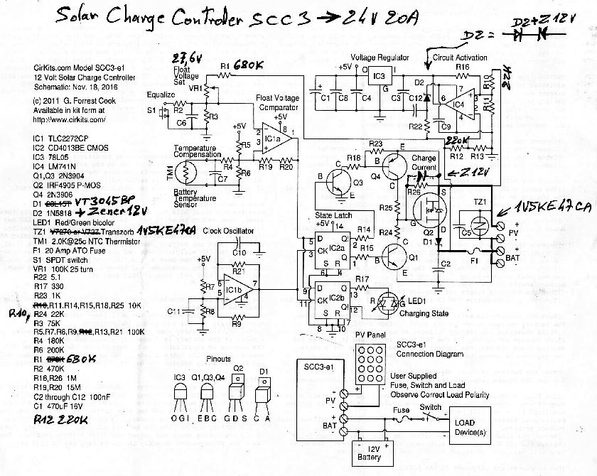
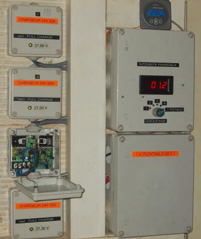
Bernard Drapier (amateur radio station FY1LE) has modified the SCC3-e1 to work with a 24V PV/battery system and has generously volunteered to share his work. Here is the modified schematic and here is a photo of his system with four modified SCC3 boards. Note that R26, the 1M resistor across the Q2 Source and Gate terminals may be omitted, the resistor may be left in the circuit if desired. The two additional 12V zener diodes can be 1N5242 types or similar. The transzorb (TZ1) can be changed to either the 1V5KE47CA as shown in the modified schematic or a Panasonic V747.
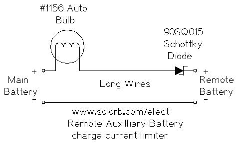
The above circuit may be used if you wish to charge a remote secondary battery, an example would be a 12V battery in a portable lamp. The #1156 lamp limits the secondary battery's charge current to a maximum of 2 amps, it also protects the remote wiring from high currents in the event of a short circuit. The wiring should be rated to handle more than 2 amps of current, #14 gauge wire or heavier is recommended. Other lamps may be used for setting different maximum charge current values.
The Schottky diode prevents a load on the main battery from discharging the secondary battery. The diode has about a .5V drop under load, so the secondary battery will always stay .5V below the main battery's maximum (float) voltage setting. A wet cell lead acid main battery and a gell cell remote battery will work well in this configuration since the float voltages for gell cell batteries are lower than for wet cell batteries.
A kit version of the SCC3 solar charge controller circuit is available from CirKits.com, buying the kit will allow you to get your solar system up and running quickly so you can focus on your solar applications.
Back to FC's Solar Circuits page.