

(C) 1999, G. Forrest Cook
Power this project from sunlight with a CirKits solar power circuit kit.
|
|
|
|
|
|
| Solar Charge Controller | Solar Power Center | Dark Activated Switch | Low Voltage Disconnect | Battery Voltage Monitor |
|
|
U1:		LM324N quad op-amp
U2:		78L12 12 volt regulator
Q1:		IRF521 N channel MOSFET
D1:		1N4004 silicon diode
LED1		Red LED
C1:		0.01uF ceramic disc capacitor, 25V
C2-C5:		0.1uF ceramic disk capacitor, 50V
R1-R4:		100K 1/4W resistor
R5:		47K 1/4W resistor
R6-R7:		3.3K 1/4W resistor
R8:		2.7K 1/4W resistor
R9:		470 ohm 1/4W resistor
VR1:		10K linear potentiometer
F1:		3 Amp, 28V DC fast blow fuse
S1:		toggle switch, 5 Amps
This circuit was featured in an article in Home Power Magazine #75
(C) G. Forrest Cook 1999
A pulse width modulator (PWM) is a device that may be used as an efficient light dimmer or DC motor speed controller. The circuit described here is for a general purpose device that can control DC devices which draw up to a few amps of current. The circuit may be used in either 12 or 24 Volt systems with only a few minor wiring changes. This device has been used to control the brightness of an automotive tail lamp and as a motor speed control for small DC fans of the type used in computer power supplies.
A PWM circuit works by making a square wave with a variable on-to-off ratio, the average on time may be varied from 0 to 100 percent. In this manner, a variable amount of power is transferred to the load. The main advantage of a PWM circuit over a resistive power controller is the efficiency, at a 50% level, the PWM will use about 50% of full power, almost all of which is transferred to the load, a resistive controller at 50% load power would consume about 71% of full power, 50% of the power goes to the load and the other 21% is wasted heating the series resistor. Load efficiency is almost always a critical factor in solar powered and other alternative energy systems.
One additional advantage of pulse width modulation is that the pulses reach the full supply voltage and will produce more torque in a motor by being able to overcome the internal motor resistances more easily. Finally, in a PWM circuit, common small potentiometers may be used to control a wide variety of loads whereas large and expensive high power variable resistors are needed for resistive controllers.
The main Disadvantages of PWM circuits are the added complexity and the possibility of generating radio frequency interference (RFI). RFI may be minimized by locating the controller near the load, using short leads, and in some cases, using additional filtering on the power supply leads. This circuit has some RFI bypassing and produced minimal interference with an AM radio that was located under a foot away. If additional filtering is needed, a car radio line choke may be placed in series with the DC power input, be sure not to exceed the current rating of the choke. The majority of the RFI will come from the high current path involving the power source, the load, and the switching FET, Q1.
PWM Frequency: 400 Hz
Current Rating: 3 A with an IRF521 FET, >10A with an IRFZ34N FET and heat sink
PWM circuit current: 1.5 ma @ 12V with no LED and no load
Operating Voltage: 12V or 24V depending on the configuration
The PWM circuit requires a steadily running oscillator to operate. U1a and U1d form a square/triangle waveform generator with a frequency of around 400 Hz. U1a acts as a comparator with hysteresis and U2d acts as an inverting integrator that feeds back to U1a. Together, they produce square and triangle wave outputs. Resistor R4 and capacitor C1 set the oscillator's frequency.
U1c is used to generate a 6 Volt reference voltage which is used as a virtual ground for the oscillator, this allows the oscillator to run off of a single supply instead of a +/- voltage dual supply.
U1b is wired in a comparator configuration and is the part of the circuit that generates the variable pulse width. U1 pin 6 receives a variable voltage from the R6, VR1, R7 voltage ladder. This is compared to the triangle waveform from U1-14. When the waveform is above the pin 6 voltage, U1 produces a high output. Conversely, when the waveform is below the pin 6 voltage, U1 produces a low output. By varying the pin 6 voltage, the on/off points are moved up and down the triangle wave, producing a variable pulse width. Resistors R6 and R7 are used to set the end points of the VR1 control, the values shown allow the control to have a full on and a full off setting within the travel of the potentiometer. These part values may be varied to change the behavior of the potentiometer.
Finally, Q1 is the power switch, it receives the modulated pulse width voltage on the gate terminal and switches the load current on and off through the Source-Drain current path. When Q1 is on, it provides a ground path for the load, when Q1 is off, the load's ground is floating. Care should be taken to insure that the load terminals are not grounded or a short will occur.
The load will have the supply voltage on the positive side at all times. LED1 gives a variable brightness response to the pulse width. Capacitor C3 smooths out the switching waveform and removes some RFI, Diode D1 is a flywheel diode that shorts out the reverse voltage kick from inductive motor loads.
In the 24 Volt mode, regulator U2 converts the 24 Volt supply to 12 Volts for running the pwm circuit, Q1 switches the 24 Volt load to ground just like it does for the 12 Volt load. See the schematic for instructions on wiring the circuit for 12 Volts or 24 Volts.
When running loads of 1 amp or less, no heat sink is needed on Q1, if you plan to switch more current, a heat sink with thermal greas is necessary. Q1 may be replaced with a higher current device, suitable upgrades include the IRFZ34N, IRFZ44N, or IRFZ48N. All of the current handling devices, switch S1, fuse F1, and the wiring between the FET, power supply, and load should be rated to handle the maximum load current.
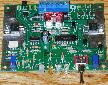
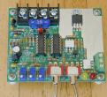
The first prototype for this circuit was constructed on an IC proto board with parts and wires stuck into the holes of the proto board. One version of the finished circuit was used to make a variable speed DC fan, the fan was mounted on top of a small metal box and the PWM circuit was contained inside of the box.
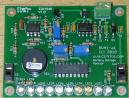
A simple circuit board (see picture) was built using a free circuit board CAD program, PCB (1) that runs on the Linux operating system. The circuit board image was printed on a PostScript laser printer onto a mask transfer product called Techniks Press-n-Peel blue film (2). The printed film is ironed onto a cleaned piece of single sided copper clad board. The board is etched with Ferric Chloride solution. Holes are drilled with a fine gauge drill bit, parts are soldered in, and the board is wired to the power and load. This technique is great for producing working boards in a short time but is not suitable for making large numbers of boards. A board pattern is shown in Fig 3, this may be photo-copied onto a piece of press-n-peel blue film, or used in a photographic etching process.
Alternately, the dead-bug construction method may be used. This involves taking a piece of blank copper PC board, glueing a wire-wrap IC socket sideways to the board with 5 minute epoxy, then soldering all of the parts to the wire wrap pins. Grounded pins can be soldered directly to the copper board.
It is advisable to check your wiring very closely before applying power the first time. Wiring mistakes can cause instant destruction of sensitive semiconductor components.
No alignment is required with this circuit.
This circuit will work as a DC lamp dimmer, small motor controller, and even as a small heater controller. It would make a great speed control for a solar powered electric train. The circuit has been tried with a 5 Amp electric motor using and IRFZ34N FET and worked ok, D1 may need to be replaced with a faster and higher current diode with some motors. The circuit should work in applications such as a bicycle motor drive system, if you experiment with this, be sure to include an easily accessible emergency power disconnect switch in case the FET shorts out and leaves the circuit full-on.
Wire the circuit for 12 Volts or 24 Volts as per the schematic, connect the battery to the input terminals, and connect the load to the output terminals, be sure not to ground either output terminal or anything connected to the output terminals such as a motor case. Turn the potentiometer knob back and forth, the load should show variable speed or light.
Jameco 1-800-831-4242 http://www.jameco.com/
Digi-Key 1-800-DIGIKEY http://www.digikey.com/

(1) Free PCB Software for Linux
(2) Techniks, Inc P.O. Box 463 Ringoes, NJ 08551 908-788-8249 Press-N-Peel
PWM PCB artwork in GIF format and in PostScript format
PWM parts silk screen in GIF format and in PostScript format
Silkscreen clarifications: the unlabeled circular pattern near LED1 is a wire jumper and the part labeled FB1 is really R9.
The connections for the 8 pin header on the printed circuit board are as follows:
Header layout as oriented
in PCB artwork:
7 5 3 1
8 6 4 2

1: VR1 clockwise
2: VR1 counter clockwise
3: 12V Supply + and Load +
4: VR1 wiper
5: 12V Supply + and Load +
6: 12V Supply -
7: Load -
8: 12V Supply -
See the variations on this circuit for more ideas.
Back to FC's PWM Circuits page.