(C) 2011-2022, G. Forrest Cook
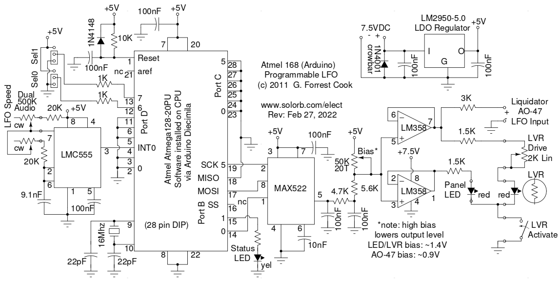
This project uses an Arduino microprocessor and a MAX522 8 bit serial DAC (Digital to Analog Converter) to produce three slightly different low frequency sine-waves. These waves can be used to drive a tremolo/vibrato circuit in a guitar amplifier such as the Lil Tiger or the Hammonator 2RVT. The LFO is also useful for driving a phaser/chorus circuit such as the Liquidator. This is an improved version of this project, the latest version of the software adds the ability to produce three waveform and also has a bias-set mode.
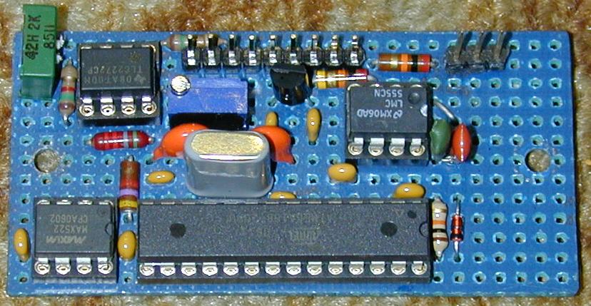
The first prototype of this project was build using the Arduino Diecimila development board and an Arduino prototype shield for the DAC and associated parts. The original assembly can be seen in the photographs of the Lil Tiger project. The next version of the circuit was built using just the Arduino's Atmega 168 (or Atmega 328) processor chip on a hand-wired perf-board as shown in the above photo, this build is slightly different than the current schematic. The third build was also hand-wired on a perf-board and is part of the Liquidator. The microprocessor should be plugged into an Arduino board to download the code. After programming, the chip should be moved to the stand-alone LFO board.
The 7.5VDC power to the board comes from a full-wave Schottky diode bridge rectifier and 2200uF filter capacitor that is connected to the 6.3VAC filament winding of a vacuum tube power supply. The 7.5V is regulated down to 5V using a LM2950-5.0 5V LDO regulator. The 7.5V and 5V sources power the op-amp, processor and DAC. Note that when this circuit is powered by an amplifier's 6.3VAC filament circuit such as in the Lil-Tiger amp, the LFO ground is not connected to the chassis ground, it is floating at 3.15VAC. The LFO circuit board should be electrically isolated from the chassis.
The LMC555 CMOS timer IC is configured as a standard multivibrator circuit, the only tricky part involves the use of a dual 500K audio taper potentiometer for adjusting the speed. Normally the frequency in such a circuit is changed with one variable resistor, however that approach does not produce a wide enough range of frequencies for an LFO circuit. By changing the value of both resistors in the timing circuit, a much wider frequency range can be achived. The two 20K resistors set the maximum oscillator speed and the 9.1nF capacitor sets the maximum and minimum speed.
The DAC is a MAX522 that is connected to Port B on the Arduino, the port is setup to use the SPI (serial) output mode. The DAC output goes to an RC low-pass circuit to remove the waveform stairsteps. The smoothed waveform is summed with an adjustable bias resistor that is used to set the lowest voltage for the waveform. The output of the voltage divider drives two sections of a LM358 op-amp. Note that the bias adjustment lowers the waveform amplitude as the bias goes up.
One op-amp section drives the front panel LED and the other drives a Light Variable Resistor opto coupler or a phase modulating transformer in the Liquidator effect. Note that the op-amp sections have a fairly low maximum output current, the 1.5K resistors limit the LED currents to a safe level. The low drive level is perfect for the opto-coupler, which uses a standard-output red LED. The front panel LED indicator should be a high-efficiency red LED for maximum brightness.
When the LFO is used to drive an LED/LVR, the bias should be set so that the LED is just turning on when the DAC is producing zero volts of output, red LEDs typically turn on at around 1.4V. When the LFO is used to drive a Hammond AO-47 vibrato unit, the bias should be set to around 0.9V. The bias adjustment can be performed by powering up the LFO circuit with the two Sel jumpers set to 5V. Connect a DC voltmeter between the circuit ground and either output of the LM358 op-amp, then adjust the bias pot for the desired voltage. Change the two Sel jumpers back to either of the other three settings and cycle the power to start the LFO.
Note that the pot motion is reversed, fast is counter-clockwise and slow is clockwise. This is a minor inconvenience that allows using a common and inexpensive dual audio-taper 500K pot, if you can find a dual log-taper pot (good luck), the operation can be flipped back to "normal".
The current Arduino "sketch" for this project is LiquidatorDACirq.ino. The sketch uses a clocked hardware interrupt to step through one of three sine waves that are selected by the two Sel jumpers at power-up. The three waves are a regular sine wave, an exponentially weighted sine wave and an inverted exponentially weighted sine wave. The regular sine wave is useful for driving a transformer-based phaser such as the Liquidator. The exponentially weighted sine wave compensates for the non-linearities in the phase shift circuit's LED/LVR opto-isolator to produce a more natural sweeping sound, it is used for the Hammonator and Lil' Tiger phase shift circuits.
The inverted exponential wave is just experimental, it can be replaced with other waves for different effects. If the circuit is powered up with the jumpers both at the 5V setting, the DAC will output its lowest voltage and no waveform. This mode is used to set the output bias voltage. Note that on power-up, the yellow LED will blink 1, 2, 3 or 4 times to indicate one of three waveforms or the bias-set mode.
The waveforms were generated by this Python language program: sinegen3.py. The program was run and the output wave tables were stored in a file and transferred into the Arduino source code using a text editor.
Back to FC's Music Circuits page.