(C) 2007, G. Forrest Cook
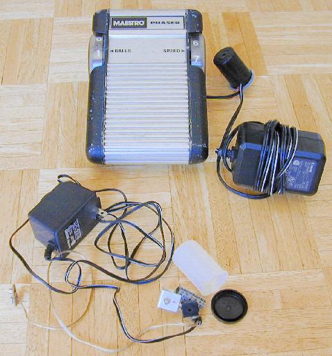
Effect pedals for electric guitars are typically powered by 9 volt batteries. These batteries cost several bucks each and don't often last very long. Leaving a pedal turned on overnight by accident guarantees a dead battery in the morning. Why spend your precious money on a constant supply of batteries when you can build this easy substitute that won't fade away right in the middle of that killer guitar solo. This device is not limited to use in guitar pedals, it can be used with guitar tuners, radios and other small 9V devices. The circuit can be built to support DC or AC wall warts, the AC version requires a bridge rectifier. I've build many of these out of surplus materials, they make good gifts for guitar players.
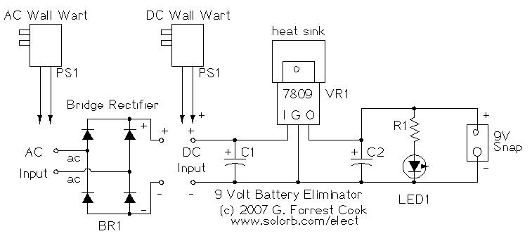
If an AC wall wart is used, the low voltage AC is sent to the input of bridge rectifier BR1. The pulsating DC output from BR1 is sent to the voltage regulator's DC input. Power from a DC wall wart should be fed directly to the DC Input pins. DC Wall wart power generally needs more filtering. C1 reduces the ripple in the DC supply. A larger capacitor may be substituted for C1, that is generally only needed for higher power loads. The smoothed DC power is fed to the input of VR1, the 7809 regulator. The 7809 produces 9V regulated DC at the output side. C2 filters load ripple on the output side of VR1. The regulated and filtered 9V DC supply is sent to the load device via 9V battery clips. The 9V DC power is also sent to an optional LED, a high brightness red LED is a good choice here, but almost any LED will work.
Wall warts can often be found for very small prices at yard sales and second hand stores. However, printed wall wart voltage and current ratings are often very inaccurate and the output voltage can drop a lot under load. It should be possible to sort through a collection of transformers to find ones that are suitable for use with this circuit. Generic wall warts with an output rating of 12VDC are usually a good bet for this application.
Before connecting the wall wart to the 9V regulator circuit, check the wall wart's output with a volt meter. The output of DC wall warts should be in the range of 11-16VDC for use with this circuit. The output of AC wall warts should be between 9-14VAC. Connect the DC wall wart supply to the regulator circuit or connect the AC wall wart to the bridge rectifier in front of the regulator circuit.
With the transformer plugged in and nothing connected to the output, measure the DC input voltage to the 7809. It should be a minimum of 11V for proper regulation. If the DC input voltage is raised too high, the 7809 may become very warm. 16V is a good input voltage upper limit. A larger heat sink and bigger container should be used if the circuit is to be used with higher input voltages and/or load currents that approach the 1 amp maximum rating of the 7809 regulator IC. If the output is at a steady 9V, connect the load (pedal) and measure the VR1 input and output voltages, the output voltage should remain at 9V and the input voltage should stay above 11V for good regulation. If the output voltage drops below 9V with the load connected, the wall wart's current rating is probably too low for the load. Substitute a wall wart with a higher current output rating.
The battery eliminator circuit is simple enough to wire with a direct point-to-point construction style. A small piece of perforated board also makes a good base for the project. Just be sure that no wires can cross if the external leads are pulled on. Small bits of black electrical tape can be wrapped around various connections to prevent shorts.
With a little effort, the regulator circuit can be built so that it fits into a 35MM film cannister. A small notch should be cut in the edge of the cannister to allow the wires to pass through. The wires should have a knot on the inside of the cannister to keep them from pulling on the internal components. The small film cannister is best for small loads, larger devices will cause the voltage regulator to get hotter and will need more air space and a bigger heat sink. For setups that approach the 1 Amp current limit of the 7809 regulator, the circuit should be mounted in a small aluminum box and the regulator should be bolted to the side of the box for good heat dissipation.
Be sure to compare the polarity of the adapter's battery snap to a 9V battery, reversed polarity can damage some guitar pedals. Some pedals use a coaxial DC power connector for auxilliary power. If you can find the appropriate mating connector, that is the preferred way to connect the battery eliminator. Be sure to observe the correct polarity on the connector, it varies from device to device.
Plug the battery snap into the pedal's internal battery connector and plug the wall wart transformer into an outlet, connect the guitar and amplifier cables and you're ready to go. It may be possible to use one of these power adapters for more than one effect, this depends on the effect's battery ground polarity as well as the current consumption of the combined pedals. Generally, it is best to use one power adapter per effect pedal, this also lowers the the chance of creating hum from a ground loop.
If the DC device you wish to power uses something other than 9V, this circuit can be adapted. For a 6V DC ouput, replace the 7809 regulator with a 7806 regulator. A 3V DC output can be achieved by using an LM2737ED-3.3 device, those can be purchased at Jameco.com. In general, the input voltage to the voltage regulator should be a few volts higher than the output voltage or the regulator won't be able to do its job. If the input voltage is too high, the regulator may run too hot.
Wall warts are famous for being "phantom loads" that waste power 24-7-365 if they are left plugged in. If you leave a bunch of wall warts plugged in all of the time, your monthly energy bill will go up. A multi-outlet switched plugstrip makes a good master power switch for a guitar amp and some assorted wall warts, and it will save wear and tear on your amp's power switch.
PS1: Wall Wart power transformer, 12-16VDC or 9-14VAC
BR1: 1 Amp bridge rectifier (used with AC transformer only)
C1: 1000uF 25V electrolytic capacitor
C2: 100uF 25V electrolytic capacitor
VR1: 7809 voltage regulator
R1: 680 ohm 1/4W resistor
LED1: high output red type
Aluminum heat sink, TO-220 size
9V battery snap connector or coaxial DC connector
 battery snap conectors may be scavenged from an old 9V battery
plastic film cannister or other plastic box
Back to FC's Music Circuits page.