(C) G. Forrest Cook August 28, 2003
This circuit serves as an ultra-low power replacement for multiple LED on-off indicators, it can display four bits of information. The display is easy to read in full daylight and consumes very little power.
The display that was used has three digits and 2 decimal points for a total of 23 segments. Different groupings of segments can be used for the four indicators. I chose to use three squares wired together (shown on) and the three lower segments wired together (shown off) for the four indicators. Many other combinations of segments could be used, one possibility would be to hard-wire numbers or letters for each of the digits. Other LCD displays could also be used for different effects.
A part that doesn't exist as far as I know, but should, is a single pixel LCD indicator that uses just 2 wires like an LED. An LCD manufacturer could probably make a lot of money with such a part. If such a part exists, I'd love to hear about it. Lacking this type of part, more complex LCDs can be used for this application as shown here. An LCD from a discarded electronic device could also be used for this project if you can find one that has accessible connections.
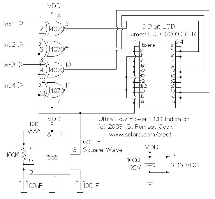
Operating Voltage: 3-15V (5V Nominal) DC
Operating Current: 250 microamps to 1 milliamp (400 microamps at 5V)
Operating Frequency: approximately 60 Hz
The 7555 IC (CMOS 555 timer) generates a square wave clock signal at approximately 60 hz. This signal is sent to the LCD backplane as well as the inputs of the four CMOS 4070 XOR gates. If the other input (ind*) of an XOR gate is low, the gate's output is a square wave that is in-phase with the clock signal. If the ind* input is high, the gate's output is out-of-phase with the clock.
Sending a signal to an LCD segment that is in-phase with the backplane signal causes the segment to stay blank. Sending an out-of-phase signal to the LCD segment causes an AC waveform to be applied to the segment which turns it black. Multiple segments are wired in parallel to generate the desired display patterns. The LCD segments require a tiny amount of current to operate, the CMOS gates also take very little power, hence the efficient nature of the circuit. It is necessary to tie the unused segments to the LCD backplane, otherwise they may partially turn on.
If more dislay bits are needed, additional XOR gates and LCD segments can be connected in the same manner. Up to 23 XOR gates could be used to drive the entire display, but at this level of complexity, a microprocessor and driver software would probably be a better solution.
If low current operation is not required, other logic families could be used to make this circuit. The circuit could be built with a standard 555 timer chip and a 74LS86 TTL XOR gate (different pinout), for example.
One thing to be aware of is that some LCDs may not operate at very cold temperatures. The Lumex components are specified to will work from -30C to +75C.
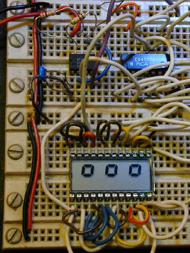
The circuit was built on a standard prototyping plug board as shown in the above photo. It could also be built on a perforated circuit board and hand-wired or a custom circuit board could be designed and fabricated. All of the parts can be purchased for under ten dollars.
The four inputs of the CMOS 4070 IC can connect to outputs on a microprocessor, or any other logic output that needs monitoring. The supply voltage of this circuit should be the same as the driving logic's supply voltage.
A fun extension to this project can be done by adding another 7555 timer chip wired as a second oscillator which can clock a CMOS counter and demultiplexer such as a 4017. The outputs can be fed to the four 4070 inputs to produce a chaser type of display. This can all be powered directly from a small photovoltaic (PV) panel, no battery is required. A small voltage regulator such as a 78L12 type should be used between the PV panel and the LCD circuit's power input to stabilize the supply voltage.
1X Lumex LCD-S301C31TR 3 digit LCD display (from Digi-Key), or equivalent
1X CMOS 4070 quad XOR Gate, a CMOS 4030 should also work.
1X 7555 or 555C CMOS timer chip
2X 100nF capacitor
1X 100uF 25V electrolytic capacitor
1X 10K 1/4W resistor
1X 100K 1/4W resistor
Other LCDs that could be used for this project include the Lumex LCD-S101D22TR, a large single digit 7-segment LCD, the GooDisplay EDC004 and EDC006 single digit LCDs and the Orient Display OD-202 2 digit LCD and OD-103T 1 digit LCD. AliExpress, eBay, DigiKey and Mouser are good places to look for a variety of LCDs.
Back to FC's Electronic Circuits page.