

Support this site by buying a CirKits kit.
|
|
|
|
|
|
| Solar Charge Controller | Solar Power Center | Dark Activated Switch | Low Voltage Disconnect | Battery Voltage Monitor |
|
|
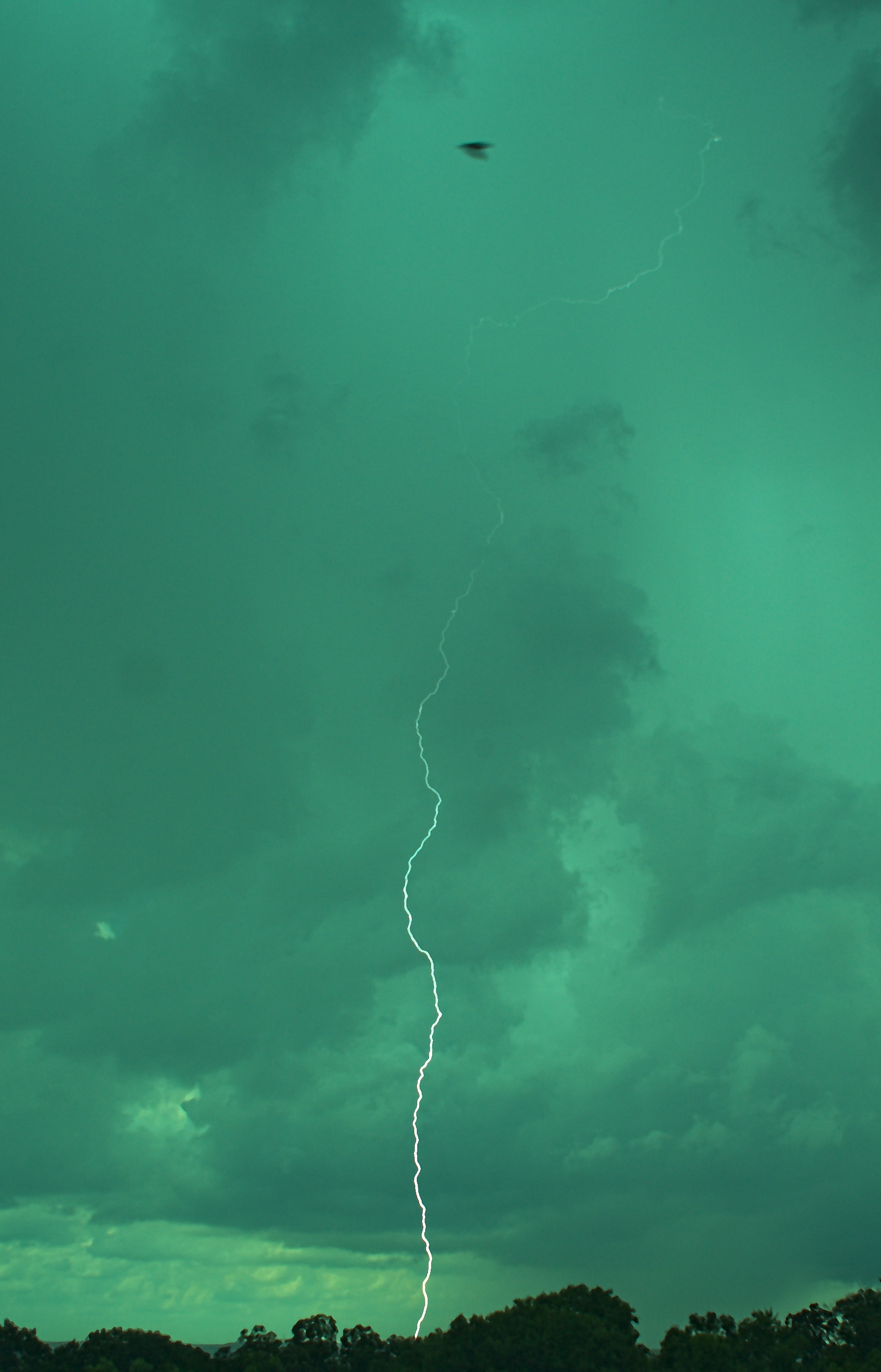
These photos were taken using the lightning trigger circuit.

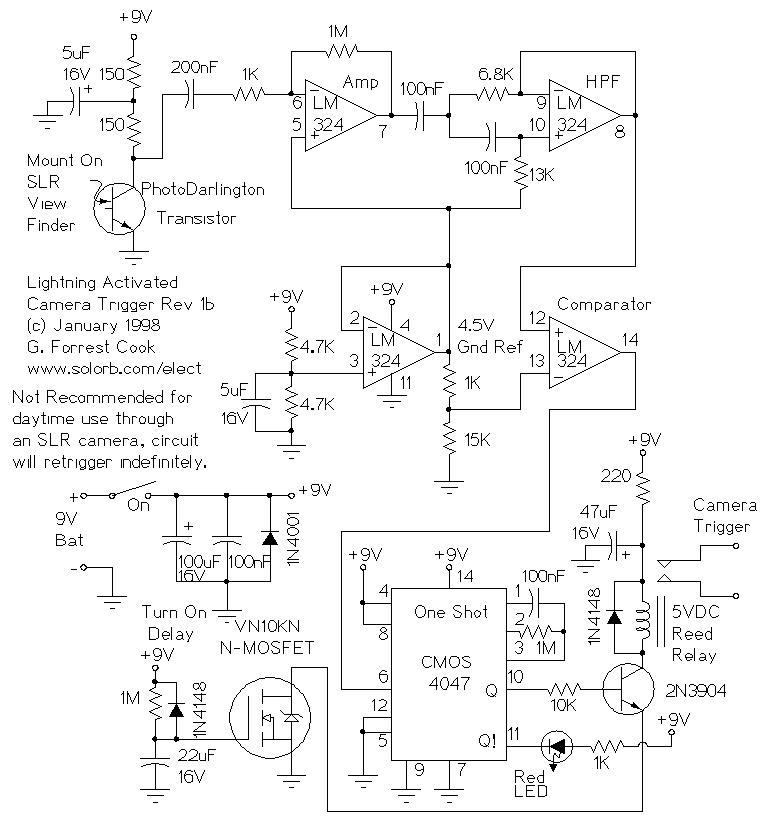
This circuit is used to trigger a camera's electronic shutter circuit when a flash of lightning is present. The circuit can also be used for photographing fireworks displays and other events tht involve bright flashes of light. The detector can be used for pointing at the sky to see if a storm is electric, it can detect flashes of light that are too faint or quick to see with the human eye.
The detector can also be used as a remote indicator of nearby lighthing strikes. The circuit could be mounted in a waterproof enclosure outdoors, the power source and the detector output could be connected by a long multi-conductor wire to an indoor observation location. Be sure to use shielded wire that is grounded at the power supply.
The PDB-V113 photovoltaic detector converts light pulses into electrical pulses. The 1998 version of this detector (see Resources below) used a photo-darlington detector. The photovoltaic detector detects lightning pulses through a much wider range of background lighting compared to the photo-darlington.
Two LM324 op-amp sections amplify the electrical pulses from the detector and are wired with a low-pass action to remove radio frequency interference. Capacitor C1 and resistor R2 and capacitor C4 and resistor R4 act as a high-pass filter to remove low frequency signals. Together, the filters produce a band-pass action which lets the pulses produced by the lightning through while removing unwanted noise.
The third LM324 op-amp is wired to produce a 4.5V reference voltage which is used for the first two op-amps and the comparator stage. The fourth LM324 op-amp is wired as a comparator, which detects electrical pulses that are slightly lower than the 4.5V reference voltage. The output of the comparator stage drives an optional piezo-electric monitor speaker as well as the following one-shot stage.
A CMOS 4001 quad NOR gate is wired as a pair of one-shot timers. The one-shot on the right side of the schematic stretches the detected lightning pulse to a few hundred millisecons, which is long enough to trigger the output circuit and camera shutter. The one-shot on the left side of the schematic is trigggered after the first one-shot and acts to hold off the output pulse, this prevents multiple triggers outputs from happening in quick succession. Resistor R12 and capacitor C9 produce a power-on delay that prevents the output from triggering when power is first turned on.
Two LEDs are connected to the outputs of the one-shots to indicate the trigger pulse and the hold-off delay. If the detector is used in bright conditions, it is a good idea to use ultra-bright LEDs for the indicators, a true green LED would be a good choice for the Trigger LED.
The two IRFD110 MOSFET transistors are wired as a bipolar pair, which acts like a fast relay contact. The transzorb protects the MOSFETs from high voltage transients produced by any inductive circuitry that is driven by this device. A pair of 24V zener diodes wired cathode-to-cathode in series can be substituted if the V727 cannot be found. The bipolar MOSFET output and transzorb are optional, the circuit provides a convenient output closure that works with either polarity. A simpler polarized output circuit can be built using just one IRFD110 MOSFET with the source pin grounded and the load connected to the drain pin.
Resistor R15 and capacitor C12 are used to provide filtered 9VDC for powering the op-amp. This voltage is further filtered through resistor R16 and capacitor C13 to provide a low-noise bias voltage for the photovoltaic detector.
The most unusual part in this circuit is the PDB-V113 blue-enhanced photovoltaic detector, made by Advanced Photonics, Inc. It was purchased from DigiKey.com. A less expensive detector that should work in this circuit is the Osram BPW34, available from Jameco.com as part 1621132. Almost any small photovoltaic cell should work as the detector in this circuit, smaller cells will have less internal capacitance which should give better response to quick flashes of light. Different photovoltaic detectors will likely require adjusting the value of R1 to achieve the most sensitive bias point.
The rest of the parts used in this circuit are jelly bean types that that are widely available from many sources.
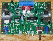
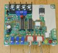
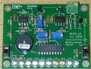
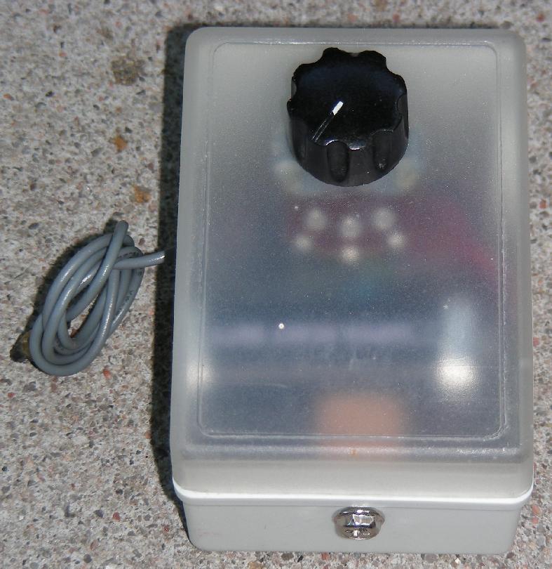
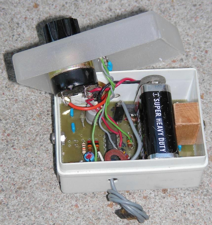
The circuit can be built on a small piece of perforated circuit board material using a point-to-point wiring technique. A hand-etched circuit board was produced for the second version of this circuit as shown in the above photos. The circuit board should be mounted inside of a small plastic case, a 35mm slide case was used in this build. Holes were cut in the case for the trigger wire, the piezo speaker, the sensor, the mounting screws and the sensitivity potentiometer. The LEDs are mounted on the circuit board and shine through the front of the case.
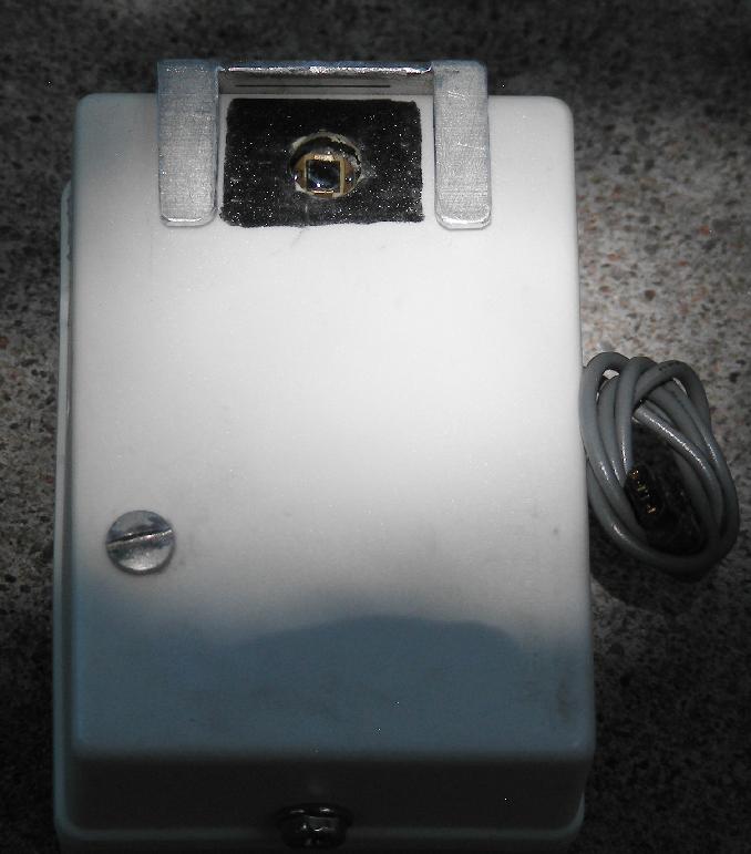
The photovoltaic detector can be mounted in a hole on the back of the box. A small metal clip was fashioned to slide over the camera's viewfinder and hold the detector in place. The above photo shows a metal clip that works with Nikon cameras, there is a small gap between the clip and the detector's plastic case. The plastic case was painted black around the sensor to reduce reflections. Unfortunatly, different camera manufacturers use different viewfinder mounts, so one or more custom mounts may be required if you use multiple cameras.
When this circuit was originally built, film-based cameras were the norm and digital cameras were just becoming available. Digital cameras are much preferred since film and processing is now very expensive. The usage info below is for film photography, most of the concepts can be adapted for digital photography. One reader has reported success using a Canon Digital Rebel EOS camera with this circuit.
The camera should be set up on a tripod, the lightning trigger should be physically secured to the camera. Slower film speeds will improve the ability to capture lightning photos. I have had good luck with ASA 100 and 200 speed film, both color and black and white film have been used.
The camera setting depends on the model used, I have taken many good shots with a Nikon N2000 camera in auto-exposure mode. A newer Nikon N70 responded too slowly in auto-exposure mode, try using a manual exposure mode with a tight F setting and a long time duration.
When shooting through the viewfinder of an SLR camera, there may be problems photographing against a bright sky. Daytime use may cause the circuit to retrigger indefinitely because the SLR's viewfinder goes black then bright when the photo is taken, causing a series of false detections. For daytime use, it is a good idea to mount the detector inside a black tube. The tube should be cut to a length that gives the detector an angle of view that is similar to the camera's lens setting. The back of the tube should be covered with something black to prevent light from entering the back side.
When dealing with large thunderstorms, lightning strikes often create a conductive path, then strike multiple times through the same path. This type of strike is the easiest to photograph. The most difficult strikes to catch are single zaps in the daytime. Daylight photos require short exposure times, lowering the chances of a zap being photographed.
When using this circuit, be prepared to run through a lot of film or digital memory, an active storm can empty a 36 exposure roll in just a few minutes. Different storms have different "personalities", some storms will produce a lot of quick and nearly invisible zaps, while others will light the sky up with a continuous series of large and bright lightning bolts.
Be sure to keep the detector pointed away from sources of flickering light such as street lights, fluorescent lights and LED lights, these will cause false triggering. It is normal for the circuit to activate constantly when in the presence of indoor lights. The lightning detector can be tested by pointing it at a bright sky and interrupting the light by passing your fingers between the sky and the sensor.
If you get any good photos using this circuit, I would love to see them.
Lightning storms can be extremely dangerous and are potentially fatal. It is best to use the circuit to photograph storms that are many miles away from the photographer. Always keep an eye on the sky, storms can reform overhead fairly quickly. Never sit on top of a hill or in an open field when storms are nearby. It is possible (and advisable) to use this setup from inside of a house or car, just make sure to turn off all interior lights to eliminate false detections.
Back to FC's Electronic Circuits page.