(C) 2014, G. Forrest Cook, W0RIO (formerly WB0RIO)

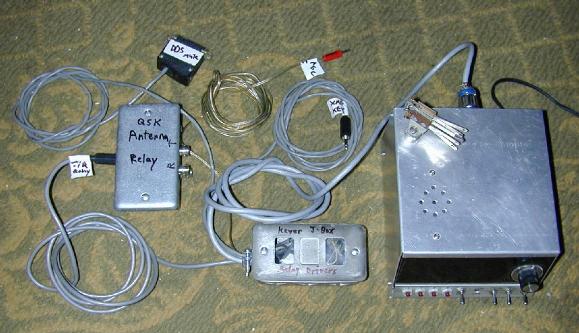
Antenna Relay, starfish hub box, interface cables and Accu-Keyer
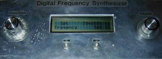
The Direct Digital Synthesis VFO based on an A&A Engineering circuir board
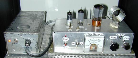
The 40-30 CW transmitter with an earlier version of its power supply
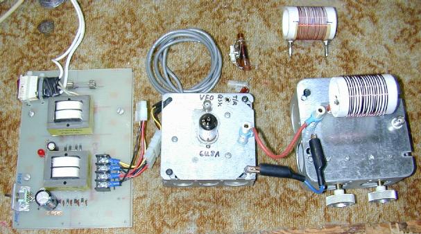
Power supply, the Little Chickadee transmitter and modular PI output filter
|
|
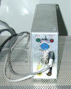
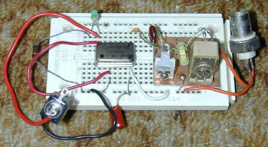
| 40 meter MOSFET xmtr | An experimental 15 meter crystal oscillator QRPp transmitter |

This is a meta-project, a collection of smaller projects that go together to form a larger system. The objective is to assemble a modular ham radio Morse code (CW) transmitter/receiver system with full break-in (QSK) capabilities and digital frequency control. A secondary objective is to construct a platform in which prototype transmitters can be built without the need to rebuild the entire system. Some of the ideas used here resemble concepts found in software design.
By using standardized connector types, a variety of different components can be easily plugged in and used in different combinations. Common sections such as the keying system, T/R relay, VFO and receiver can be used with different transmitter modules for operation at different frequencies and power levels.
Most of the transmitters used in this project started out as stand-alone projects, they had to have minor modifications to work with the standardized wiring required by this system. This system allows even the simplest transmitter designs to work with QSK capabilities. My future transmitter designs will be compatible with this system.
Some of the components used in this project use potentially lethal high voltages including 120 VAC, high voltage DC and high voltage RF. The project should only be taken on by someone who has experience working with high voltage circuitry. When working on any high voltage sections of this project, power should be disconnected and the power supply capacitors should be discharged.
Initially, the keyer was a 1970s vintage WB4VVF Accu-Keyer board in a box with a 5V DC power supply, the All-Ears QSK Timing Generator circuit and the Smooth Tone Clickless CW Sidetone Generator circuit. The original Accu-Keyer and QSK circuit has been replaced by my Accu-Keyer Extended, which features a number of improvements over the original Accu-Keyer. The multiple outputs from the keyer circuitry are sent to a junction box called the starfish hub, which routes the signals to the VFO, the transmitter, the transmitter power supply, the antenna relay and the receiver's AGC control. Wiring details for the starfish hub are shown in the All-Ears QSK Timing Generator page.
Photos of four transmitter modules are shown, they include the 40-30 CW Transmitter, the Little Chickadee 6U8A QRP Transmitter, an IRF510 MOSFET transmitter that was based on a QST magazine article from the 1990s and an experimental 15 meter QRPp transmitter that consists of a 21.0526 Mhz solid-state oscillator feeding a low-pass filter. This experiment eventually became part of my 15 Meter QRP Transmitter project.
You can see how I restored an antique boat anchor transmitter and interfaced it to the modular QSK system in the Harvey Wells T-90 restoration article. The radio performs nicely and is much more frequency-stable now that it is controlled by a DDS VFO.
The Little Chickadee transmitter is split into two modules, one for the transmitter and associated circuitry and another for the PI output filter. All of the transmitters are powered by external power supplies. This shows how larger modules can be divided into smaller reusable modules. All of the transmitter VFO inputs and RF outputs use BNC jacks. All of the transmitter keying signals use the same stereo 3.5mm plugs and jacks, which drive the different external components. The 40-30 transmitter uses the inverted Active signal to control the power supply ballast load. The Harvey Wells T-90 uses this signal to control its internal T/R relay.
The VFO module consists of a DC power supply, an A&A Engineering DDS VFO board and a 68HC11 controller microprocessor board with control switches and an LCD display. The DDS VFO connects to the various transmitters via a BNC cable. It also has a mute line that connects to the keyer's junction box. This is a fairly dated VFO, it produces frequencies from 1 Hz to 8 Mhz, although harmonic spurs start to increase above around 7.1 Mhz. It is still useful for the CW end of the 40 meter band. The DDS board produces a 0.5V peak to peak sine wave that is buffered by a NE5205 20dB broadband RF amplifier IC.
The VFO output needs to go through a frequency multiplier circuit when operating above 7.1 Mhz. The 40-30 transmitter has a built-in doubler circuit for operating on the 30 meter band, the VFO is set to 5.05 Mhz in that situation. The Harvey Wells T-90 transmitter also has a built-in multiplier and works with the DDS set to either the 3.5 Mhz or 7 Mhz bands. There are a number of newer DDS ICs such as the AD9834, the AD9851 the Si570 and the Si5351, all of these can produce direct frequency outputs up to and above 28 Mhz.
The antenna relay box contains two reed relays, a control input jack and three BNC jacks. The first relay is an SPDT mercury-wetted device that connects the antenna jack to either the receiver or the transmitter. The second relay is an SPST device that shorts the receiver input to ground during transmit to prevent overload. The QSK timing generator provides the signal that switches the relays, the antenna relay is never switched with live RF on the contacts. Power through a small reed relay should be kept below 100 Watts. Wiring details for the antenna relay are shown in the All-Ears QSK Timing Generator page.
The receiver module can be one of several choices. The main receiver used in this system is an antique Drake 2B, it has the ability to have its AGC speed externally controlled by selecting different capacitors by an SPDT reed relay. The AGC is set to slow during receive and fast during transmitting. Other receivers and transceivers have been used with this setup including a Kenwood TS430-S, a National NC-155, the experimental House Finch Direct Conversion Tube Receiver and the Meadowlark Direct Conversion Tube Receiver.
A variety of construction methods were used for the various parts of this system. See the individual project pages for details. Numerous steel electrical utility boxes were used since they are inexpensive and provide acceptable RF shielding. All of the control wiring is done with shielded cables. Standard romex cable clamps were used for many of the cables going to and from the utility boxes.
Any and all of the modules in this system can be easily exchanged with newer designs. Potential future modules include a VXO-VFO, a DDS VFO with more frequency range, a more powerful T/R relay and of course, more transmitters.
I plan on adding a connection between my Sound Card Interface and the Accu-Keyer for computer-controlled keying (cheating).
The first step is to plug everything in for a given configuration. I usually leave my 40-30 transmitter plugged in by default. Once everything is plugged in and powered up, operation is just a matter of tuning the transmitter to the antenna and using the keyer paddles to transmit. The QSK circuitry makes the T/R switching fully automatic.
Switching transmitter modules is fairly easy. Just power off one tranmitter and move the VFO, keying and RF output connectors to the second transmitter before powering it up. The VFO output level may need to be adjusted for a particular transmitter. My VFO has a variable output control and each transmitter has a unique optimum input level. A future revision may involve setting the VFO to the highest output level and adding a variable attenuator to the input of each transmitter.
Back to FC's Ham Radio Circuits page.