(C) 2011, G. Forrest Cook
This project is a power-on boot sequencer, aka the boot-kicker, that works with PC-style computers such as an ATX or Mini-ITX system. These computers use power supplies which stay partially energized and can be enabled with a low voltage switch closure. Some computers have built-in BIOS functionality that can be set to boot up the computer when AC power is applied, others do not. This circuit is intended for the latter type of computer.
A desktop PC can be used for a variety of dedicated purposes such as a home automation controller, a burglar alarm or an automatic motion-operated camera. Such a system needs to be able to automatically restart when the AC mains power drops out and comes back on. A battery-backed uninterruptible power supply (UPS) is normally a good solution for this problem, but if the power remains off for long enough the UPS battery will drain and the computer will eventually power down.
This circuit can be used to manage computers that are located in remote locations. It is also useful for automatically booting typical desktop computers.
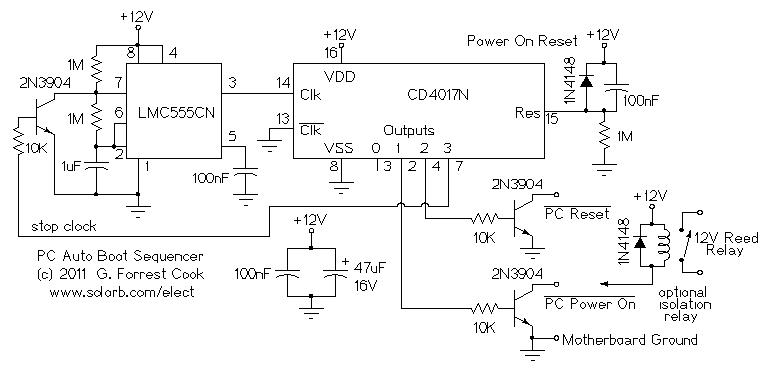
This circuit provides the necessary timing to virtually press the PC's power-on switch and the PC's reset switch in sequence. If the PC uses an external 12V power supply such as a Mini-ITX device, power for this circuit can come from the PC's power supply. For larger desktop systems, it may be necessary to power this circuit with an external 12V DC supply such as a wall-wart.
When 12V power is applied to the circuit, the reset pin on the 4017 counter/demux chip is momentarily held high by the components on the 4017 reset pin, insuring that the 4017 starts with output 0 active. The LMC555 timer IC is wired as an oscillator with an approximate frequency of 1/2 Hz. The first clock pulse from the LMC555 is longer than the others due to the way the timer chip starts up. During this time, the 4017 output 0 stays high.
After the first low to high transition from the LMC555, the 4017 chip's output 0 goes low and output 1 goes high. This turns on the lower 2N3904 transistor and pulls the PC power on line low. The next clock pulse from the LMC555 causes the 4017 chip's output 1 to go low and output 2 to go high. This causes the PC power on line to go high, switching on the power supply. The pc reset line goes low at this point.
The next clock pulse from the LMC555 causes the 4017 chip's output 2 to go low and output 3 to go high. This releases the PC reset line and allows the PC to boot. The 4017 output 3 line turns on the 2N3904 that is connected across the LMC555, preventing the timer chip from making any more pulses. This competes the boot sequence and the circuit stays idle until power is removed and reapplied.
In the Mini-ITX system that this circuit was built for, the PC power-on signal and the PC reset signal were both available from 2 pin headers on the motherboard. As previously mentioned, the Mini-ITX computer's power supply produces power as soon as the AC input powwer is live. In this setup, the two control lines were tied to the collectors of the two 2N3904 transistors and the +12VDC power and ground lines were connected to the power supply input on the computer.
If your computer does not provide 12V when the mains power comes on, be sure to connect the ground side of the power-on circuit to the motherboard ground, this should be available on one wire from the 2 pin reset connector. The optional reed relay can be used if the PC's power supply activation line does not share a common ground with the motherboard, normally this is not required.
The circuit can be wired in parallel with the original power and reset switches or it can be connected directly to the motherboard with two 2-pin headers. This disables the manual switch functions, but they are not required when the circuit is connected.
The circuit was built on a small piece of perforated circuit board using IC sockets and point-to-point wiring. A pre-drilled prototype circuit board would also make a good platform for the circuit. The circuit can be mounted inside of the PC, just make sure that it does not short out to the case or any of the wiring inside of the PC.
Apply power to the computer, wait a few seconds for the sequence to complete and watch the computer boot.
Back to FC's Computer Boot Management Circuits page.